Become a MacRumors Supporter for $50/year with no ads, ability to filter front page stories, and private forums.

Vagus

macrumors newbie
Original poster
May 1, 2023
8
0
Hi,

I am not an electronics' specialist.

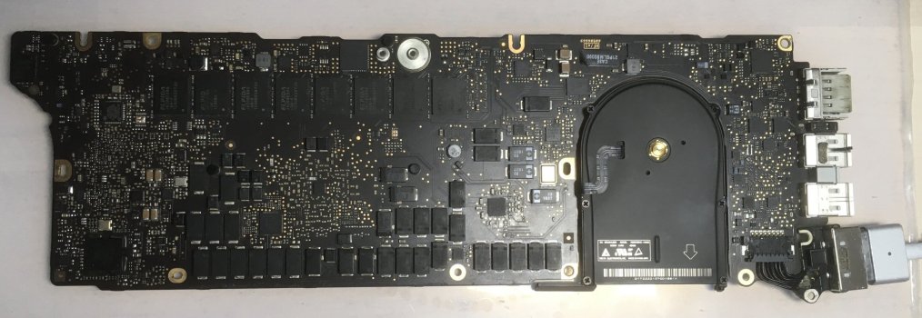
A week ago I replaced the battery in my old but perfectly working MB Pro. This was its second battery change since purchase. The new battery was aftermarket but listed as "original"!

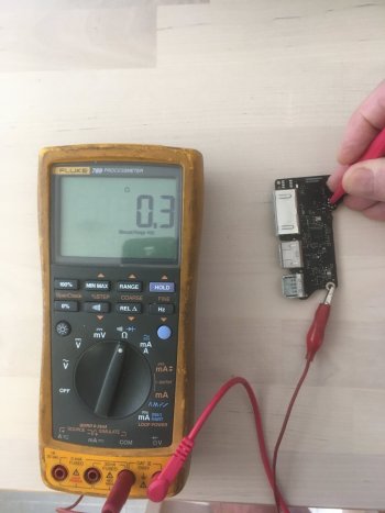
After connecting the charger, the LED on the Magsafe lit up green, switched to orange, then dimmed and finally went out after 2-3 seconds. The laptop won't boot and the fans don't turn. I have tried resetting the SMC and bypassing the SMC by connecting the charger after depressing the start button. Nothing works. I spent 2 days searching for signs of component damage. There are none. The laptop has never had liquid spilt on it. After pulling my hair out, I took the laptop to a small repair shop as neither Apple or an Apple-recommended shop would touch it due to its age and the fact that I had already changed the battery. The repair shop got no further than I but neither of us had access to the circuit diagrams or boardview. Thus, everything I have tried has come from web posts and videos: some very informative but none has solved the problem. If anyone can offer troubleshooting advice based on the following measurements, I would be very grateful.

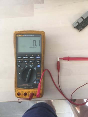
These are the voltages on the pins of U7000 with the charger only connected (i.e; no battery):

1. 15.29
2. 16.05
3. 0.002
4. 3.398
5. 0.002
6. 3.3
7. 0.002
8. 0.001
9. 0.001
10. 3.428
11. 0.559
12. 3.427
13. 3.397
14. 0.008
15. 0.047
16. 0
17. 0.054
18. 0.042
19. 5.51
20. 5.52
21. 0
22. 0
23. 0.005
24. 0.005
25. 5.22
26. 0.497
27. 0.497
28. 0.495

Resistance between pins 17-18 is 3.6 ohms and between 27-28 is 20.4 ohms.

As there is no voltage on pin 14, I gather the system controller cannot function but, as the computer won't boot when bypassing the SMC, there must be a further problem.
 

Attachments

  • IMG-3313.jpg
    IMG-3313.jpg
    261.8 KB · Views: 372
  • IMG-3315.jpg
    IMG-3315.jpg
    280.3 KB · Views: 93

DeltaMac

macrumors G5
Jul 30, 2003
13,480
4,411
Delaware
And, now you don't have any response from the magsafe LED? It never comes on now, after that first plug-in to magsafe?
That LED sequence (green first, then changing to orange) sounds completely normal - but then dimming to off is not.
Probably blew out a voltage regulator, or at least some chip in the power circuit somewhere. Or, something just failed due to age in that power circuit.
Your best bet would be a repair shop that does circuit board repairs. Sometimes you get lucky on that, but that luck usually needs you to live near a large city, where finding that level of repair is more likely.
 

Vagus

macrumors newbie
Original poster
May 1, 2023
8
0
Yes, correct, no light on the charger; no boot. The bigger repair shops where I am charge 100 euro an hour and won't touch it and I don't want them to try at that rate or it will cost me much more than the computer is worth. If I don't luck out finding someone that had the same problem and found the fix, I doubt I'm going to be able to save what was a great computer.:(
 

DeltaMac

macrumors G5
Jul 30, 2003
13,480
4,411
Delaware
You could try replacing the DC-in board, which is the board with the magsafe port.
Here's some repair steps that are needed to do that:
I suggest that as a not-too-expensive part, which can possibly be the issue.
And, you know how to remove the logic board, so replacing the DC-in port would be simple for you.
If that does not help, then you can decide if you want to make the effort (and expense) to find a replacement logic board.
That should be the fix, then.
 

Vagus

macrumors newbie
Original poster
May 1, 2023
8
0
I am pretty sure the DC in board and connector are functioning correctly and I doubt it’s worth investing in a new motherboard given the laptop’s age - sadly. Thank you for the suggestions, though. I’m pretty sure that I can track down the problem if I can get my hands on the circuit diagrams and boardview to identify the components and their performance criteria. That may take a while, I guess.
 

real_mon2

macrumors member
Mar 11, 2023
49
8
Windsor, Ontario, Canada

Locate the 820-**** number that will be marked on your logic board. Post it here for a confirmation.

The magsafe logic operates from the 3v42 power rail. Check this voltage to ground. Using a soft start logic, the original power adapter has a dual color led that operates over the Dallas Semiconductor single wire interface.

Next is ppbus_g3h key power rail that needs to be confirmed.

Review the above. Suggest for you to open a thread on badcaps in the laptop forum of badcaps to proceed with the repair. We can continue the investigation after your feedback.
 

Vagus

macrumors newbie
Original poster
May 1, 2023
8
0
Pin 11 of U7000 was shorted. The short remained after removal from the board indicating fault with the SMC. Additionally, on removal of U7000 from the PCB, pads 15, 16 and 17 lifted, so I took the decision to stop further effort to resurrect the motherboard. Disappointing that a simple battery change can kill off a perfectly functioning computer.

Thanks for your efforts to help.
 

Vagus

macrumors newbie
Original poster
May 1, 2023
8
0
It's now September and I have had some, but not yet total, success. I found a replacement logic board for sale at a good price so bought it. Fitted it in my MBP and the computer started up fine but I had neglected to connect the six-wire plug coming from the right-side I/O board, so Mac OS X flagged the missing wifi hardware. After connecting the I/O board, the computer wouldn't start. A key-press SMC reset (shift, control, option, power) followed by a hard reset (connect the Magsafe with power button depressed) causes the computer to boot so long as the I/O board is NOT connected.

The above suggests either that replacing the battery also damaged a component on the I/O board or I damaged its wiring when failing to connect the I/O after logic board replacement. I do not have a schematic to determine what voltages should be present on those 6 wires or whether any of them share connections on the I/O board. When I measured the resistance of of each wire between the plug and the board to determine if any had internal breaks, I found no internal breaks but some wires are electrically connected to more than one I/O board contact, which suggests that they either share board connections or shorts are present on the board.

Can anyone offer advice about what could be going on?

Many thanks in advance.
 

real_mon2

macrumors member
Mar 11, 2023
49
8
Windsor, Ontario, Canada
Consider to test with a known good io flex cable and/or known good io board. Both are inexpensive on AliExpress. If available on Amazon, it will be a better option so that you can return what you do not need after this investigation. The cable is marked with a silk screened part number.
 

Vagus

macrumors newbie
Original poster
May 1, 2023
8
0
Consider to test with a known good io flex cable and/or known good io board. Both are inexpensive on AliExpress. If available on Amazon, it will be a better option so that you can return what you do not need after this investigation. The cable is marked with a silk screened part number.
Thanks but it's not the flex ribbon; it's the six wires that are bundled together which supply ground connections, 5V and 3.3V to the I/O board. Last night, a member of the Ifixit forum kindly sent me the wire designations and PP5V_S4 (wire 4) is shorted to ground. If I could find a circuit diagram I could trace that circuit to find the faulty component(s) before resorting to AliExpress.
 

real_mon2

macrumors member
Mar 11, 2023
49
8
Windsor, Ontario, Canada
So to confirm the issue, PP5V_S4 on the io board is shorted? If yes, the method to locate the shorted component is to use voltage injection. Before starting, connect this io board to the main motherboard. Remove all power. Meter in resistance mode. Check the resistance to ground of PP5V_S4. What is the exact resistance to ground measurement of this rail?

Still with no power, use an external power supply and dial it to 1 volt (not higher). Inject this 1 volt onto the same shorted rail. Check on which part heats up. Often a shorted tantalum capacitor will heat up and crumble due to the low internal resistance. Post your updates.
 

Vagus

macrumors newbie
Original poster
May 1, 2023
8
0
Correct. Thank you for the procedure. Exact resistance to ground is 0.0 ohms. My regulated power supply is currently in storage, so it might take me a few days to get to this. Before that, I should remark that the ceramic capacitor closest to the board connection of PP5V_S4 (see image) while in circuit is reading short to ground on both sides. I will remove it later to check but I have no idea what replacement value would be required if it needs to be replaced.
 

Attachments

  • Suspect faulty capacitor on 820-3199A.JPG
    Suspect faulty capacitor on 820-3199A.JPG
    534.5 KB · Views: 62

real_mon2

macrumors member
Mar 11, 2023
49
8
Windsor, Ontario, Canada
All components on this rail will appear to be shorted. Flux it well and use a hot air tool or a soldering iron that should dispense enough heat but low air pressure to melt each side of this tiny capacitor. Do not melt or lose the nearby parts. Be patient. After the solder melts, remove the cap with tweet. Allow the board to cool down and then test the board for the same resistance again. If the resistance is much higher, attach it to your logic board and test again.

At 0 ohms, that is a hard short. Be sure that you are measuring the correct points on the cable. If possible, post a pic with your measurements and cable pin #. Will check against the main logic board connector once at the office. The logic board is documented with the connector pinout but do not recall an io board schematic. Check for visible shorts. Be sure your meter resist scale is correct.
 

Vagus

macrumors newbie
Original poster
May 1, 2023
8
0
All components on this rail will appear to be shorted. Flux it well and use a hot air tool or a soldering iron that should dispense enough heat but low air pressure to melt each side of this tiny capacitor. Do not melt or lose the nearby parts. Be patient. After the solder melts, remove the cap with tweet. Allow the board to cool down and then test the board for the same resistance again. If the resistance is much higher, attach it to your logic board and test again.

At 0 ohms, that is a hard short. Be sure that you are measuring the correct points on the cable. If possible, post a pic with your measurements and cable pin #. Will check against the main logic board connector once at the office. The logic board is documented with the connector pinout but do not recall an io board schematic. Check for visible shorts. Be sure your meter resist scale is correct.
I think I am going to struggle with the equipment I have and by the time I purchase the right tools for the job and component(s) it think it will be cheaper to replace the entire I/O board from AliExpress, as you first suggested. Nonetheless, I attach two photos showing the resistance of my probe wires and the resistance between PP5V_S4 and the board. I had to use a crocodile clip to ground in order to free up one hand, hence the 0.2 ohm difference from the previous reported reading when probe resistance is subtracted. My meter probably does need to be calibrated, so you are correct to suspect that the reading of 0.0 ohm may not be accurate.
 

Attachments

  • Probe resistance.JPG
    Probe resistance.JPG
    284.4 KB · Views: 46
  • PP5V_S4 to board.JPG
    PP5V_S4 to board.JPG
    288.7 KB · Views: 45
Register on MacRumors! This sidebar will go away, and you'll see fewer ads.