Become a MacRumors Supporter for $50/year with no ads, ability to filter front page stories, and private forums.

protocold

macrumors member
Original poster
Jul 10, 2019
97
35
I was stupid enough to accidentally touched the PSU [ACBEL Model OT8043 PSU. (Apple P/N: 614-0444)] with the CPU heatsink during a logic board removal for an iMac 21.5 2010 and heard a pop sound with some sparks and is now dead [PSU was plugged into the logic board during removal and logic board is still fine when tested in a different machine]

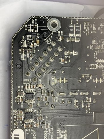
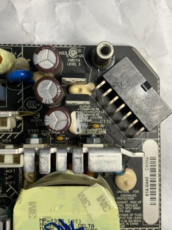
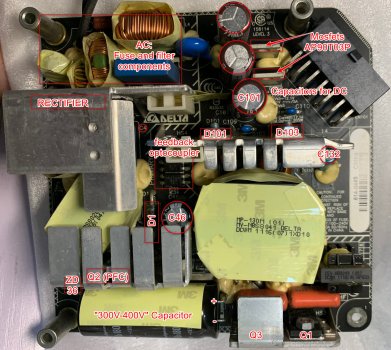
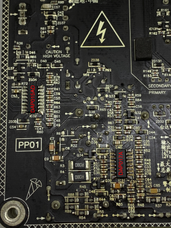
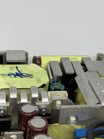
This has left some blackened burnt evidence near the electric shock logo [at C001] as shown in the below picture. (I think that's approximately where the heatsink touched it)

IMG_6198.png


IMG_6193.jpg


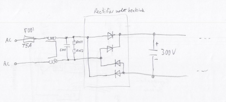
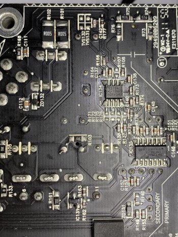
I have very limited knowledge of electronics and circuit. With that, I used multi-meter and found that the fuse F001 is blown. C001 is not shorted. That's all I know at this point. The IC on the right near the middle of the below picture is NCP1605G and the one on the bottom middle is L6599AD.

What would be my next step in terms of further troubleshooting this? Do you think C001 is burnt? Should I just try to replace the fuse and plug it in again and see what happen?

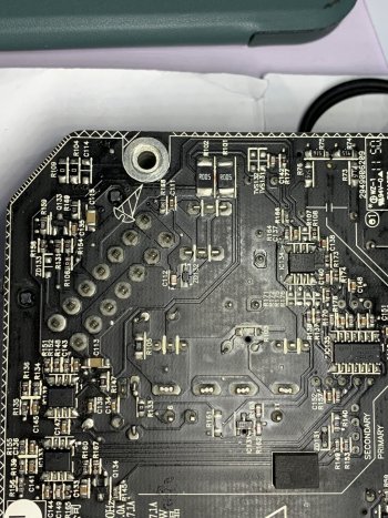
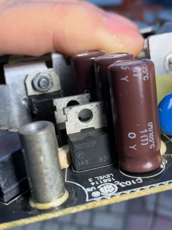
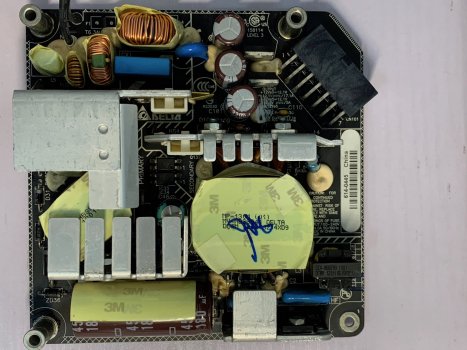
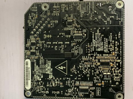
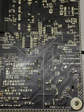
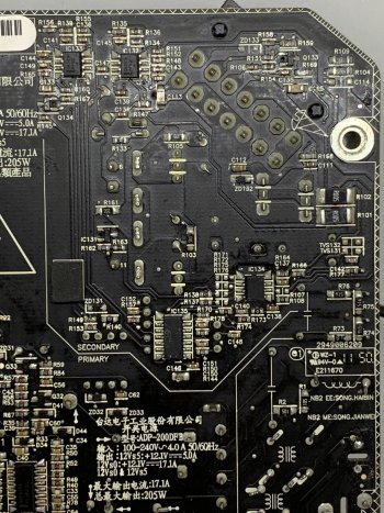
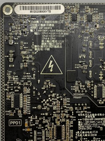
I am attaching a few more pictures of the PSU. Greatly appreciate any kind of help.

IMG_6196.jpg


IMG_6199.jpg


IMG_6194.jpg
 
Last edited:

USB3foriMac

macrumors 6502
Apr 15, 2020
311
116
Singapore
C001 will not be defect. It didn't have voltage at the time (it's across the AC), and even suddenly applying a voltage to it would not cause any damage.

That F001 is blow would mean that an excessive current flow occurred. Was the AC plug still plugged in when this short circuit occurred? If so, indeed it will only be F001 that will need replacement, but leaving the plug in when doing such work would be a high risk to your life, so you should never do this again.

If the plug was removed, then there is no voltage at the point of F001. The voltage is kept in the large capacitor with the print "T1022 PET" on it in your last picture. This capacitor will be the only one holding a voltage, which is around 300V to 400V.

So now comes the question: if the power plug was removed, what would cause F001 to blow?
The rectifier would not allow any voltage from the large capacitor to "go backwards" (i.e. towards F001).

So I'm not really sure how you managed to cause a current through F001, but anyway it is likely that only F001 was affected in your case. C001 definitely not, and it is very unlikely that any of the semiconductors is affected.
The only other component I see possibly at risk is the rectifier.
1646371630357.png

It's hard to follow the tracks, so use the help of my schematic (or try to look at the marking which should show +~~- or so) to identify the diodes and check (with the multimeter in diode test mode) whether you have approx. 0.3V-0.7V across each diode and in one direction only. If so, the rectifier is ok, and I would just replace the fuse and switch on and see what happens.
 

Attachments

  • rough schematic of AC input.jpg
    rough schematic of AC input.jpg
    77.1 KB · Views: 191
Last edited:
  • Like
Reactions: Nguyen Duc Hieu

Danfango

macrumors 65816
Jan 4, 2022
1,294
5,777
London, UK
Just a heads up, from someone who used to design SMPS, these things are extremely dangerous to debug and repair if you have limited electronics experience. In failure conditions, such as duff bleeder resistors, they can maintain lethal voltages across capacitors even when turned off for a long time. I would attempt to locate a complete replacement module on eBay rather than repair it.

As for the actual problem, if F001 is blown when the power supply was powered down, that suggests too much current went through it so you'd need to work out where that current went. Based on standard SMPS topology the only two things that could have gone bang are on the primary side are the main switching MOSFET and the controller. Neither are particularly worth futzing with if they have blown up. I would just replace the whole assembly.

I spent a lot of time repairing SMPS in old electronic test gear and literally the things tend to blow up 4-5 times before you find the actual cause and you really need safety kit to do it properly. In my case I had isolation transformer, isolated scope probes and a nice plexiglass box to put over it to catch flying MOSFETs 🤣
 

protocold

macrumors member
Original poster
Jul 10, 2019
97
35
C001 will not be defect. It didn't have voltage at the time (it's across the AC), and even suddenly applying a voltage to it would not cause any damage.

That F001 is blow would mean that an excessive current flow occurred. Was the AC plug still plugged in when this short circuit occurred? If so, indeed it will only be F001 that will need replacement, but leaving the plug in when doing such work would be a high risk to your life, so you should never do this again.

If the plug was removed, then there is no voltage at the point of F001. The voltage is kept in the large capacitor with the print "T1022 PET" on it in your last picture. This capacitor will be the only one holding a voltage, which is around 300V to 400V.

So now comes the question: if the power plug was removed, what would cause F001 to blow?
The rectifier would not allow any voltage from the large capacitor to "go backwards" (i.e. towards F001).

So I'm not really sure how you managed to cause a current through F001, but anyway it is likely that only F001 was affected in your case. C001 definitely not, and it is very unlikely that any of the semiconductors is affected.
The only other component I see possibly at risk is the rectifier.
View attachment 1967680
It's hard to follow the tracks, so use the help of my schematic (or try to look at the marking which should show +~~- or so) to identify the diodes and check (with the multimeter in diode test mode) whether you have approx. 0.3V-0.7V across each diode and in one direction only. If so, the rectifier is ok, and I would just replace the fuse and switch on and see what happens.

Many thanks for your help! I have measured the rectifier and the middle 2 pins are the ~ ~ and each of these pins have one way connectivity to the top/bottom pin so I think the rectifier is fine!

I am not too sure if I had the AC plug on.. I have the fuse on order already and let me just replace it and then put on goggle & plug it in to see what happen!

One more silly question, when the heatsink touched C001 (lets assume the AC plug was on), since the logic board was still plugged onto the PSU via the dc side of the PSU, what had actually happened?
 
Last edited:

protocold

macrumors member
Original poster
Jul 10, 2019
97
35
As for the actual problem, if F001 is blown when the power supply was powered down, that suggests too much current went through it so you'd need to work out where that current went. Based on standard SMPS topology the only two things that could have gone bang are on the primary side are the main switching MOSFET and the controller. Neither are particularly worth futzing with if they have blown up. I would just replace the whole assembly.

Many thank for your advice too! Could you further enlighten me on how the main switching MOSFET and the controller would gone bang? [noob: where exactly are they in my pictures?!]
 

Danfango

macrumors 65816
Jan 4, 2022
1,294
5,777
London, UK
The controller is one of the ICs on the bottom in a SOIC package on the live side of the board. The switching MOSFET will be attached to one of the heatsinks on the primary side. You will have to look up the parts and match them.

As for going bang, they are actually extremely low voltage devices at the gate input on the MOSFET and anywhere on the controller IC. Any short could have dropped the peak DC voltage through one of the low voltage circuits which will cause the MOSFET gate to explode. That may also blow the fuse because MOSFETs tend to go closed circuit until they melt or explode. When they're powered up they sound like a shotgun going off. Probably what caused my hair to fall out :D
 
  • Like
Reactions: iCtheDUDEabides

USB3foriMac

macrumors 6502
Apr 15, 2020
311
116
Singapore
Many thanks for your help! I have measured the rectifier and the middle 2 pins are the ~ ~ and each of these pins have one way connectivity to the top/bottom pin so I think the rectifier is fine!

I am not too sure if I had the AC plug on.. I have the fuse on order already and let me just replace it and then put on goggle & plug it in to see what happen!

One more silly question, when the heatsink touched C001 (lets assume the AC plug was on), since the logic board was still plugged onto the PSU via thedc side of the PSU, what had actually happened?
If the AC plug was still in and you short the heatsink (conductive metal) between the C001 point and one of the adjacent points, you short the AC which bows the fuse. For the spark to occur at the C001 point,you put the heatsink first one an adjacent point, then touch the C001 point.

I am highly confident that in your case, neither the controller nor the MOSFETs are blown.

And BTW: you don't need exactly the identical fuse. This is a slow acting 5A fuse. You can use medium or fast acting with same or even lower rating. You should avoid using higher amperage though in order to avoid greater damage.
If you have such fuse at home, solder it in to test. You can still replace later with the correct one.
 
Last edited:

protocold

macrumors member
Original poster
Jul 10, 2019
97
35
I am not sure if i touched any adjacent points as I couldnt tell (other place has no burnt mark)... but likely so...if so, why wouldnt it cause whatever at the other adjacent point to fail too?

But i thought the heatsink should be at GND (is it? at least on macbook pro heatsink is connected to ground) on the logic board and is there any other chance that it will make other stuff go bang?

Sorry if I am not making any sense here... it seems like my head is not clear.
 
Last edited:

Danfango

macrumors 65816
Jan 4, 2022
1,294
5,777
London, UK
If the AC plug was still in and you short the heatsink (conductive metal) between the C001 point and one of the adjacent points, you short the AC which bows the fuse. For the spark to occur at the C001 point,you put the heatsink first one an adjacent point, then touch the C001 point.

I am highly confident that in your case, neither the controller nor the MOSFETs are blown.

And BTW: you don't need exactly the identical fuse. This is a slow acting 5A fuse. You can use medium or fast acting with same or even lower rating. You should avoid using higher amperage though in order to avoid greater damage.
If you have such fuse at home, solder it in to test. You can still replace later with the correct one.
You probably can’t use a different fuse. The inrush current to fill up the filter cap will blow it instantly and lead you to think that something else is failing.

I had a whole team of engineers laughing at me when I learned that one the hard way ?
 

USB3foriMac

macrumors 6502
Apr 15, 2020
311
116
Singapore
I am not sure if i touched any adjacent points as I couldnt tell (other place has no burnt mark)... but likely so...if so, why wouldnt it cause whatever at the other adjacent point to fail too?

But i thought the heatsink should be at GND (is it? at least on macbook pro heatsink is connected to ground) on the logic board and is there any other chance that it will make other stuff go bang?

Sorry if I am not making any sense here... it seems like my head is not clear.
If you touched a single point with the heatsink, nothing would happen. The heatsink is not grounded to AC ground as the AC ground is not on the connector to the MoBo. It's only grounded when screwed in to the iMac body, which I understand you unscrewed the MoBo and when moving it you touched the PSU.

When you touch 2 points with your heatsink, it is unlikely that you touch both points at exactly the same time. So one point will be touched earlier, where there isn't any spark yet. Only when you cause the short circuit with the second point, that's when the spark occurs.
 

protocold

macrumors member
Original poster
Jul 10, 2019
97
35
Thanks for your quick reply.

I have yet another dead PSU for another iMac of the same model/year but made by Delta (ADP-200DFB) for which I can probably salvage its fuse [not blown] but it is T6.3AL instead of T5A on this one...
 

protocold

macrumors member
Original poster
Jul 10, 2019
97
35
Hurray!!... I took the T6.3AL fuse and solder it onto this board and it works!

But could we now move onto fixing the other broken ADP-200DFB? :D
 

USB3foriMac

macrumors 6502
Apr 15, 2020
311
116
Singapore
Hurray!!... I took the T6.3AL fuse and solder it onto this board and it works!

But could we now move onto fixing the other broken ADP-200DFB? :D
At some point, you should still replace the fuse with 5A or lower. Higher ratings risk that more components than necessary get damaged in case of a future fault.

ADP200DF is similar to yours as well as the ones discussed here:


Check fuse, the 3 MOSFETs, rectifier and diodes. Then report back. If you replace the fuse before having checked all those components, it is likely that your fuse simply blows again. So unless you have plenty spares, follow the steps in those other threads first.
Report status of the components you checked. The primary side will be nearly identical to the schematic I posted in my thread. Use that to follow your components. Print out the schematic, and put your component designations onto the printout. Then scan back and post here so that we know which component you are talking about.
 

protocold

macrumors member
Original poster
Jul 10, 2019
97
35
The fuse is definitely good and that is why I can take the fuse and put it onto the ACBEL OT8043 PSU to revive it. The rectifier [close to the main fuse] is good and just like the ACBEL.

If the fuse and rectifier are good, does it mean the voltage across the big cap as shown in your drawing in your first reply above for me should have good voltage ~ 390v or so?

This iMac was bought used but with bad PSU & unknown history, all I know was it didnt power on and by swapping the now repaired ACBEL PSU the iMac itself works fine. I didnt troubleshoot until now, with your help.

I took a quick look on your other threads [and will study in detail again]. I think I have found the MOSFETs: Q1,Q2 and Q3 below.

This is what i have found on youtube [in Russian language], the contributor provided the below[But I dont yet understand his markings]. I have further marked on top +/- for the bigcap on the image near the bottom, as well as Q1 and Q3, Q2 marked in yellow. I followed your instruction and to mark G,D,S for Q1 and Q3 and I hope I didnt make any mistake...I am not sure how to mark Q2?!

Assuming my markings of GDS are correct, then I was able to confirm what you had suggested in other thread:
D-S, it behaves like a diode.
G-S, 10kOhm resistor (marking: 103).
G-D, high ohmic (Megaohm).

I think i have also found the 3 pin diodes on the secondary side with large heatsink and pin 1,3 seems to have diode behaviour toward pin 2. What now?

IMG_20200505_044236.png


IMG_6215.jpg
 
Last edited:

USB3foriMac

macrumors 6502
Apr 15, 2020
311
116
Singapore
If you can read the label on Q2, you cod search for the datasheet to get the pinning.

If not, you could apply the following method:
Check out Q2 by assuming the same pinning as the others. If the measurements are nonsense, assume a different pinning and repeat.
Eventually, this will only be of concern if you find a short between two pins. If not, you can assume this component is ok.

If you got this iMac as "not working", it is likely the power supply is ok and the GPU is faulty.

I'd put a fuse back, power up (don't forget PS_ON), and check the output voltage provided the fuse or circuit breaker doesn't trip/blow.

If it works, read on "bake GPU". Disassemble, bake and reassemble, then it should be working again.

Let us know what the supply is doing.
 

protocold

macrumors member
Original poster
Jul 10, 2019
97
35
Thanks Q2 is 15N60C3. I have checked Q2 is fine.

1646663017320.png


For sure it isnt the GPU, as I said, this iMac is working fine with the repaired ACBEL PSU.

How to turn on PSU via PS_ON? Is it shorting it to GND?

I cannot find any pinout for the 21.5 model. But I found this on youtube


at 1:17 the guy short 2 pins and then 12v is shown on the multimeter. One of the pin is GND[the one on the right]. Is the other one PS_ON[2nd from the right on the bottom]?


A1311_PS_ON.png
 
Last edited:

USB3foriMac

macrumors 6502
Apr 15, 2020
311
116
Singapore
Sorry I don't have the pinning and I don't have my 21.5 iMacs any more. But it is correct to short PS_ON to ground (0V). Many of the pond will be linked. Those are either +12V or 0V, so they are easy to identify. But they will only provide voltage after PS_ON is on 0V.
There should also be one pin with 12V standby, giving you 12V all the time.
Seems you can trust the video.
I'd still recommend to search for adp200df pinning with "PS_ON" included in your search. Maybe that leads to something.

Sorry for not fully following your description.
So the Mac is working with the repaired PSU. Great. And this PSU is faulty. Got it.
If it was switched on at some point, obviously the circuit breaker doesn't trip, so Q2 isn't faulty.
Also, it means you can connect back to AC and CAREFULLY measure a bit in-circuit.
The 350VDC should be across the large capacitor.

You can check whether you measure some DC on the secondary side. After the transformer come the double diodes which you found. These are followed by another inductor, and then at least one larger capacitor. Measure across this (or in fact, any) larger capacitor whether you can find any DC.
If not, your primary MOSFETs need to be checked in more detail, or the diodes, particularly on the secondary side.
 

protocold

macrumors member
Original poster
Jul 10, 2019
97
35
I couldnt find any inductor after the double diodes... I saw these 3 larger capacitors connecting in parallel from the double diodes. Is this what you are talking about?

IMG_6215.png
 

USB3foriMac

macrumors 6502
Apr 15, 2020
311
116
Singapore
If that's your component side, can you post a photo of the back side, as the Russian pic doesn't seem to match yours?
I looked at this at my PC now, I noticed that your pic is simply distorted and rotated left. This confused me while looking at my phone, as it looked as if the connector is on the opposite side compared to the PCB photo. So ignore that. If possible, post a better photo of front and back (both upright), with lighting so that the PCB tracks become visible on the solder side. The russian pic is too small and not well lit. check for yourself whether all PCB tracks can be seen on your pics before posting.

Since you point out (and admittedly I hadn't looked), your model just seems to have those 3 capacitors after the diode. Typically, there is one of those wheel-like inductors with the copper wire. Your model apparently not. This points to a very simple design, compared to the 27" and other supplies.
And unless there is another capacitor hidden underneath the D101/103 heatsink, I don't see any other.
Check for other caps on the secondary side (not the AC), and point out if you find any. I suspect there should be one, which should be for the standby generation. Otherwise, Delta uses the 'main' 12V circuit also for standby. Or there isn't even a standby circuit. Then you wouldn't find any 12V on the connector.
I already checked my library, but I don't have much on this model. I'll check my Delta documents, maybe I find something.

It seems just between the 3 caps and the connector are two 3-pin components. Can you identify the label? They seem to be linear voltage regulators, e.g. for 5V generation, but they could be something else.
 
Last edited:

protocold

macrumors member
Original poster
Jul 10, 2019
97
35
Really appreciate your time on this. I am attaching more pic below.

After the double diodes, all I saw was 2 tiny capacitor (yellow) before going into the 3 larger cap I shown above, then they are connected to the two 3-pin components [marking 90T03P] via 2 resistor marked R005 [R101, R102].

1646707013263.png


There are also 2 ICs: DAS01A which are op amps.
 

Attachments

  • IMG_6224.jpg
    IMG_6224.jpg
    563 KB · Views: 148
  • IMG_6223.jpg
    IMG_6223.jpg
    663.1 KB · Views: 119
  • IMG_6225.jpg
    IMG_6225.jpg
    754.2 KB · Views: 177
  • IMG_6226.jpg
    IMG_6226.jpg
    424.3 KB · Views: 137
  • IMG_6227.jpg
    IMG_6227.jpg
    329.8 KB · Views: 162
  • IMG_6228.jpg
    IMG_6228.jpg
    414.7 KB · Views: 213
  • IMG_6229.jpg
    IMG_6229.jpg
    602.8 KB · Views: 422

USB3foriMac

macrumors 6502
Apr 15, 2020
311
116
Singapore
Thanks for the pics.
I also marked your earlier picture with components of interest (on the component side). I added your mosfets just now.

Check the diode D1 whether it is ok, as well as D101 and 103 if you haven't yet.
Check the AP90T03P whether they are ok. Same as the other ones, just make sure you follow the right pinning as in your datasheet.

If you switch ON the supply (and you can ignore the PS_ON for the moment), you can check out the voltage on the primary (AC) side. There is a capacitor C46 which I would be interested in what voltage it has.

On the secondary, check whether you have voltage at C101 (and the other two, which I believe should be in parallel, but maybe not), an C132.

If you have voltage, you have to find the PS_ON (just try as per video). Check whether the output voltage now is present at the connector, and what it is.
Depending on your results, we can narrow down where to search.

And one more thing: if possible, keep the same orientation for the pics throughout. Use the orientation like the pic I posted here: when on component side, the connector is on the top right; when on solder side, the connector is top left. This confused me already several times when looking at your pics, hence some confused instructions from my end earlier.
 

Attachments

  • component w markings.jpg
    component w markings.jpg
    721.3 KB · Views: 344

protocold

macrumors member
Original poster
Jul 10, 2019
97
35
Sorry for the confusion on pic orientations, I have fixed them above[and included some more hopefully clearer pictures below]. My pack of fuse hasnt arrived yet so I will have to put the old fuse back before I could do live testing. Let me try to do that.

FYI. I would like to point out that there are more components under the the Q2 heatsink (D2, Q31 and C45 which I have marked on top of your mark up below), in the russian youtube video it seems like it was a troubleshooting to conclude C45 was bad, replacing it fixed the author's PSU[he was using a reference application design schematics in L6599 datasheet to illustrate his thoughts(all above my head, needless to say I was trying to understand it with the auto-translated captions)] :


My research has made me believe DAP015AD = L6599A. I am attaching the L6599 datasheet PDF as well as a diagram that he provided relating to the DAP017 chip. I cannot find datasheet for DAP017 anywhere.

component w markings.png
 

Attachments

  • datasheet.pdf
    635.9 KB · Views: 174
  • Dap017-To-Drive-Master-Pfc-Stage-In-19-Power-Supply.jpg
    Dap017-To-Drive-Master-Pfc-Stage-In-19-Power-Supply.jpg
    44.4 KB · Views: 482
  • IMG_6230.jpg
    IMG_6230.jpg
    646.5 KB · Views: 294
  • IMG_6231.jpg
    IMG_6231.jpg
    654.1 KB · Views: 210
  • IMG_6232.png
    IMG_6232.png
    4.5 MB · Views: 281
  • IMG_6233.jpg
    IMG_6233.jpg
    665.1 KB · Views: 192
  • IMG_6234.jpg
    IMG_6234.jpg
    683.2 KB · Views: 134
  • IMG_6235.jpg
    IMG_6235.jpg
    697 KB · Views: 142
  • IMG_6237.jpg
    IMG_6237.jpg
    234.6 KB · Views: 192
Last edited:
  • Like
Reactions: iCtheDUDEabides

USB3foriMac

macrumors 6502
Apr 15, 2020
311
116
Singapore
Yeah, I got that schematic already, and I marked it up as well. But it doesn't help right now as we can't progress. Randomly unsoldering components also doesn't make sense. I'll post the schematic when I'm back at the computer.
D1, D2 and q31 are probably part of the PFC circuit. Probably no fault here, but check the diodes.
 

protocold

macrumors member
Original poster
Jul 10, 2019
97
35
I also measured D3 as shown here that both directions seems to have a short[some people have also stated the same observation in other forums and said diode itself was tested good if removed(I didnt do that)]. However, I have cross checked with another known good APD-200DFB which has the same shorted D3.. what would cause this?! why didnt this matter?
[Just sharing what I saw during the search. I hope these are not distractions]

IMG_6236.png
 
Last edited:

USB3foriMac

macrumors 6502
Apr 15, 2020
311
116
Singapore
I also measured D3 as shown here that both directions seems to have a short[some people have also stated the same observation in other forums and said diode itself was tested good if removed(I didnt do that)]. However, I have cross checked with another known good APD-200DFB which has the same shorted D3.. what would cause this?! why didnt this matter?
[Just sharing what I saw during the search. I hope these are not distractions]

Ok, here is my marked schematic. this schematic is an application note of the L6599, and this circuit is close but not identical to the ADP-200DFB.

L6599 application example marked.jpg


Note that the designations are not the same. So when you compare, make sure you identify the parts according to their interconnection. Also, some parts of the circuit can be different. I don't have the ADP-200DFB any more to compare, but from what I can see from the pics, it is very similar. If parts/circuits are same, then the value can still be different, as this is a generic schematic, and not the actual supply.

So take it as guidance.

D3 is close to an inductor (the thing wrapped in yellow and covered by heatsinks to a large extend). In above schematic, I suspect D3 is indeed D3 or D4 of the schematic. I have looked at the solder points of that inductor, and can only find 2.
I believe the circuit is more close to the 27" model like here (from ON Semiconductor, document TND316/D):
1646731522618.png

Quite similar to above,only small differences. L1 is just an inductor, L2 in the upper picture shows a double coil. Maybe you can see it better on the actual part; how many coils/pins does the inductor have? And does one side connect to the "+" of the rectifier!

In general, diodes are sometimes in parallel to coils/inductors. So you always measure a near short circuit.
In this case, you wouldn't measure a short, at least not in both direction. If in both directions, this could also be an indication for a nearby faulty components which short the "+" to "-" and hence closes the loop for the diode.

In such case, either continue searching until you have clearly found the faulty part, or if in doubt, unesolder one pin, and then measure.

With an accurate schematic, you could easily identify such matter, but due to absence of such, it is more difficult.
 
Register on MacRumors! This sidebar will go away, and you'll see fewer ads.