For C42, if I use meter on ohm mode at 200K setting, I can only see it stable at 42 and it isnt moving..
This is possible. In the schematic above, there is R69/R74 resistors which are basically in parallel to the capacitor, which probably affects your measurement. As long as you don't measure a short, it's ok.
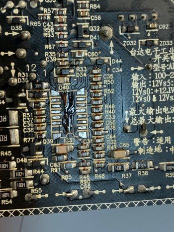
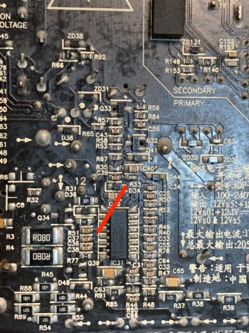
For Pin 16 HV, the circuit seems to be quite different and more complicated.. it is connected to GND via C63 and also to D31 and D32 on the component side and then I dont know where it goes...
If you have a capacitor to GND, that's fine. It buffers the voltage supplied to the IC.
D31 and D32 should then go to the high voltage (the 300V-400V cap, + side).
You can also occasionally find that for the NCP1605. This is to avoid a negative voltage on HV in reference to VCC. VCC pin has the capacitor, and if this is still charged but the 300V capacitor (for some reason) isn't, then you would have a negative voltage between HV and VCC which apparently could damage the internals. So I am confident this isn't to worry about.
Pin 13 seems to be quite different too, would that because on the DA017A it is marked as OVPDelay but on NCP1605 it is marked as STDWN (shutdown)?! Pin 13 is connected to GND via C37 and also to Q39...
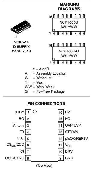
I found the pinout of DAP017A which seems to be very similar if not identical to NCP1605 [STBY = Skip_Adj?, STDWN=OVPdelay?]
The place where I usually order stuff only has NCP1605 so I ordered it instead of DA017A.. am I going to have trouble?
To the above 3 points, they all go back to the question: Is DAP017A same as NCP1605?
The web does not give anything on DAP017/DAP017A/DAP017AH. The schematic provided by one guy in the web is from DAP011, so not exactly applicable.
Let us look at the Pins first.
As you noted, only Pin 1 and Pin 13 are different. The rest carries the same designation.
So can we conclude the other pins the same? Can we conclude these ICs do the same?
Let us look whether we can answer that.
It is also possible that DAP017A and NCP1605 are totally different products. But they are used at the same spot, with the same function (power factor correction). LiteOn, who designed some if not all of Apples power supplies, have very similar designs among all their supplies. Compared to the ADP-310AF from the 27" iMac, the design is of the primary is nearly identical.
Another point, which however does not relate to the function of the chip: On Semiconductor who owned DAP017A (and NCP1605), went through several acquisitions during that time. It is possible that the DAP017A came from one of these acquisitions, and the naming scheme was then changed to NCP1605 to be in line with other products.
Let us look at the pin 1 and 13.
Pin 1: Skip_adjust. If you read up on NCP1605, you can read that Standby skips cycles in low demand mode. Skip_adjust sounds as if this performs the same function.
"The NCP1605 automatically skips switching cycles when the power demand drops below a given level. This is accomplished by monitoring the Pin 1 voltage that must receive a voltage below 300 mV in light load conditions.
Practically, a portion of the feedback signal of the downstream converter (or some other signal able to indicate that the power demand is low) should be applied to Pin 1."
I'm fairly confident that the pins do the same. At least, both are input pins. So electrically, this shouldn't cause damage, but it is possible that the internal electronics are indeed different. So it is possible that NCP1605 does not work.
Pin 13: OVPdelay versus STDWN.
From NCP1605:
"Apply a voltage higher than 2.5 V on Pin 13 to permanently shutdown the circuit. This pin can be used to monitor the voltage across a thermistor in order to protect the application from an excessive heating and/or to detect an overvoltage condition.
To resume operation, it is necessary to decrease the circuit V CC below V CC RST (4 V typically) by for instance, unplugging the PFC stage and replugging it after V CC is discharged."
OVPdelay (overvoltage delay) sounds different to such description, but I can't imagine what a delay would have to do with overvoltage. Maybe delay a switch-off if there is overvoltage? I don't know.
It is possible that the circuit was changed on this pin, and that DAP017A is simply an older version of NCP1605.
So how can we be a bit more sure?
Try to find out - and make a sketch (best with close-up photo of your DAP017A) - how pins 1 and 13 connect in the circuit. This will probably tell us a lot more whether NCP1605 is really compatible.
If you want to take a (admittedly small) risk, just replace DAP017A with NCP1605. Electrically I'd say you won't cause damage of NCP1605 or other parts of your supply, but there is a chance NCP1605 isn't entirely compatible. You could then take another minor risk by connecting pin 13 to GND as i the application note schematic.
Unless there is someone providing a datasheet for DAP017A or having proof that they are the same part (just different vendors, for example), it is impossible to say whether this is fully compatible or identical.