Thank you mosaiko! I already solved the problem long ago with that floppy drive. It was the Hall sensors that failed.
At first, I tried with no luck with the RPM measurement method (using audio recording, as described in earlier posts). It was not giving any hint toward the hall sensors being broken. But now I suppose that the controller was still able to keep the mean speed at a good rate, even if the rotation could be unbalanced by a broken sensor. Now that I think of it, I should have put more "sounding spots" on my test floppy disk.
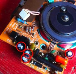
As a last try, after checking that every other part on the motor board was good (and before trying to replace the motor controller itself) I replaced the hall sensors H1 and then H2 and the drive started working ok.
Since those sensors are really hard to find... (I'm not doing that for advertisement) I'm going to tell you people where I bought mine:
http://www.aliexpress.com/snapshot/6499659460.html
THS103A HALL SIP4 100% NEW ORIGINAL MARKING 3H 50PCS/LOT
Last but not least, after some months the drive began to not spin anymore when parked in certain specific spots, so I also replaced H3. Everything seems to be good now. Those sensors really seem to get broken easily.
")