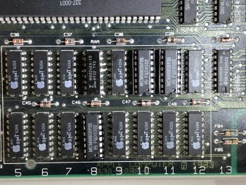
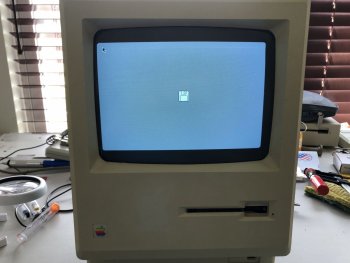
I am the original owner of a 128k Mac from my first year at Drexel University in 1985. I am trying to restore it back to operating condition. When I powered it up I got the Chime and then the Sad Mac Icon with code 040820 was displayed with a good quality screen picture. So I replaced RAM chips G8 and F10. After that I powered it up and got the Chime and then the Sad Mac Icon with code 020040 was displayed, also with a good quality screen picture. So I replaced RAM chip F11. Now when I power it up I no longer get a chime, the screen comes on with basically a white/black static display, and I get random static sounds out of the speaker. See two links to videos of the current symptoms. Any idea what might have gone wrong with my second RAM chip replacement, or other ideas of what could be wrong now?
Become a MacRumors Supporter for $50/year with no ads, ability to filter front page stories, and private forums.
Macintosh 128k No Chime and Strange Sounds. Need Help to Restore.
- Thread starter Joe_D
- Start date
- Sort by reaction score
You are using an out of date browser. It may not display this or other websites correctly.
You should upgrade or use an alternative browser.
You should upgrade or use an alternative browser.
Check continuity from chip to chip of each pin in each Row
ie, all RAM chips in row Fxx should have pin to pin continuity
AND all RAM chips in Row Gxx should have pin to pin continuity
It's likely that when you replaced F10, one of the data-lines was severed, and didn't reach F11 (the next error after repair).
IIRC, one pin should not have continuity within a row. However, that pin should have continuity to the corresponding column chip below it. If I'm correct, that should be pin 3.
Last edited:
Thanks for the feedback! I rechecked pin to pin continuity with one probe on F5 and the other probe on the corresponding pin of F12. Went through all pins on both sides of the RAM and then repeated for row G. All pins checked out good with the exception of what you mentioned. Pin 3 on one side and pin 2 on the other side of the RAM chip are not connected across the row for either row F or G. That seems to be normal. I also checked continuity between adjacent pins on F11 and there were no shorted pins. So unfortunately, the pin continuity through the traces on the PCB does not seem to be a problem. I also had another new RAM chip so i changed F11 with a different new RAM chip, but still have the same issue on power up.
Disconnect the floppy drive (when powered off) - then try reading the voltages again.I read +11V, +11V, +5V, and -12V on the three you identified plus the one to the right of the 5V.
Also, check CR5 (diode mounted to the heatsink) at the top of the board. It's resistance in-circuit should read 3.6k in one polarity and infinite resistance in the other polarity.
The voltage measurements came out exactly the same with the floppy drive disconnected.
The diode measured over-limit in one direction, and 659 ohms in the other direction. I repeated a couple of times to ensure the 659 Ohms was the reading.
The diode measured over-limit in one direction, and 659 ohms in the other direction. I repeated a couple of times to ensure the 659 Ohms was the reading.
According to Larry Pina that's a bad flyback transformer.The voltage measurements came out exactly the same with the floppy drive disconnected.
The diode measured over-limit in one direction, and 659 ohms in the other direction. I repeated a couple of times to ensure the 659 Ohms was the reading.

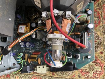
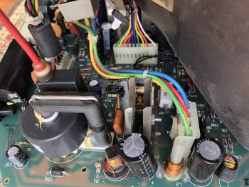
Is one of the heat sinks at the top of the board discoulred a blue/purple or brown?
Some pics of the analog board may also help.
I agree it would be unfortunate if it is the FBT. Though Larry's quick CR5 check does seem to indicate it.
Some pics of the analog board may also help.
I agree it would be unfortunate if it is the FBT. Though Larry's quick CR5 check does seem to indicate it.
Some analog board pics attached. I replaced Q3 once about 15 years ago. It was getting so hot that it almost melted the solder. Everything worked good after replacement. Just felt it now and it is fairly hot to the touch after only a couple of minutes of on-time.
Attachments
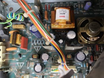
Do you recall if the heatsink was that color all those years ago ?
My experience is that the heatsink being that dirty color, it has experienced a bad or partially shorted FBT. The Question is when.
However, if the heatsink is too hot to touch after a short time, the FBT is probably toast.
Options are to buy a used MacPlus that at least produces a picture, or a replacement FBT.
A new BU406D is also recommended.
from https://forums.macrumors.com/threads/flyback-transformer-for-mac-plus-1mb.2241496/ :
The only two VERY EXPENSIVE source I've found is DalbaniCorp in the USA and Donberg - below link is NOT an endorsement - Buyer beware.

 www.donberg.ie
My experience is that the heatsink being that dirty color, it has experienced a bad or partially shorted FBT. The Question is when.
However, if the heatsink is too hot to touch after a short time, the FBT is probably toast.
Options are to buy a used MacPlus that at least produces a picture, or a replacement FBT.
A new BU406D is also recommended.
from https://forums.macrumors.com/threads/flyback-transformer-for-mac-plus-1mb.2241496/ :
The only two VERY EXPENSIVE source I've found is DalbaniCorp in the USA and Donberg - below link is NOT an endorsement - Buyer beware.
157-026C Flyback 157026C / Replaces Apple / HR 42031 | eBay
All credit cards are processed with Authorize.net. © 1982-2015 Dalbani. Serving the Electronic Industry Since 1982. Miami, FL 33166. 4225 NW 72nd Ave. Dalbani is a national and international distributor of high quality electronic components and parts.
www.ebay.com
Line Output Transformer / Flyback: HR42031 (HR 42031) - 1570026B APPLE 157026C MONITRON...
hr 42031, 1570026b apple 157026c monitron 157126v macintosh
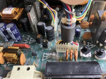
I am pretty sure the heat-sink was already that color from the first time I replaced Q3. But it does get fairly hot to touch quickly now. What do you think about those gaps in the top of C15, C16, C17? I can't recall if those were there before I had the issue.
They are normal. These caps have a HV Spark Gap for protection....What do you think about those gaps in the top of C15, C16, C17?
If the Flyback transformer is shorted, would there be any picture at all on the screen? I still get the white/black snowy screen. No bong/chime on power up now though.
Today I used a higher resolution multimeter to do the readings. The 5V was at 4.69V so turned the POT to bring it up to 5.00V. No change to the issue though. With this meter CR5 reads 10M in one direction and 21k ohms in the other. So it seems it is ok. Other readings I took which seem normal:
CR19 6.08V
CR18 12.22V
R46 22.5 ohms
R47 0.8 ohms
R48 100.5 ohms
R49 0.8 ohms
R50 1.6 ohms
R51 15 ohms
R52 10.21k ohms
CR1 4.6M/21.8k ohms
CR5 10M/21k ohms
CR20 116/180 ohms
CR21 38/38 ohms
Only other items that Larry Pima points out to test would be the TSM chip on logic board, Q1 chip on logic board, and Q3 chip on analog board. All require desolder and test out of circuit. I might start with Q1.
Pulled Q1 on the logic board and did the out of circuit test:
K-O 11.7k 11.15k ohms
I-O Inf 3.65M ohms
K-I 3.6M Inf ohms
The I-O and K-I readings don't match the expected but are also not the typical bad reading noted by Larry. But this seems suspect. Cheap enough to replace so may pick up new part and solder in.
K-O 11.7k 11.15k ohms
I-O Inf 3.65M ohms
K-I 3.6M Inf ohms
The I-O and K-I readings don't match the expected but are also not the typical bad reading noted by Larry. But this seems suspect. Cheap enough to replace so may pick up new part and solder in.
If the Flyback transformer is shorted, would there be any picture at all on the screen?
Sad to say, yes it can. If a winding is shorted early on itself, it's possible.
At this point, other than a logic board swap as a diagnosis measure, I'm lost for suggestions.
Thanks for the help so far. Note I did install sockets on the three new RAM chips but I don't think that should be an issue. Unfortunately I do not have a spare logic board to swap in currently. So I will try the Q1 and TSA chips on the logic board after I receive the new parts.
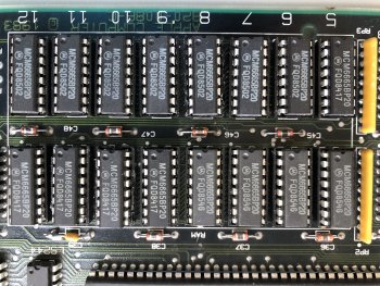
I actually just noticed the RAM I purchased is Motorola MCM6665BP20 4164 200ns chip versus the original Apple logo 4264 RAM. I need to check differences of 4164 versus 4264 as a possible issue.

MCM6665BP20 Motorola 64k Dram IC Mcm6665b 6665 - Vintage for sale online | eBay
Find many great new & used options and get the best deals for MCM6665BP20 Motorola 64k Dram IC Mcm6665b 6665 - Vintage at the best online prices at eBay! Free shipping for many products!
www.ebay.com
Attachments
Hmmm - I'm not sure what the difference may be. A quick glance over two pdfs doesn't reveal much difference (other than minor dissipation).
EDIT: I've never used these as a substitute myself, however they do appear to be used in place on C64s
 www.c64-wiki.com
EDIT 2: I suspect the 6665 may have been Motorola's own part, before the 4164 naming convention took hold.
The 1984 Motorola Memory Data Book shows a 4116 & the 6665 but not a 4164.
EDIT: I've never used these as a substitute myself, however they do appear to be used in place on C64s
RAM - C64-Wiki
EDIT 2: I suspect the 6665 may have been Motorola's own part, before the 4164 naming convention took hold.
The 1984 Motorola Memory Data Book shows a 4116 & the 6665 but not a 4164.
Attachments
Last edited:
Replaced the Q1 Linear Regulator on the logic board today. No change. The measurements on the new Q1 out of circuit were about the same as the old one so didn't expect any difference with this. The TSA chip seems like a bigger job to replace but that would be the last item on the debug list. I will dig more into the data sheets on the Memory before doing anything else but it seems that either 4164 or 4264 should work.
In researching this more there were several recommendations not to mix socketed and un-socketed RAM as it could cause timing issues. Given that and the current state of troubleshooting I decided to replace all 16 of the RAM chips with sockets and new RAM chips. In doing that I accidentally cracked the glass on the C39 capacitor just above one of the RAM chips on the logic board. I decided not to power on until I replace C39. I measured it to be 122nf. Does anyone know exactly what type of capacitor C39 on the logic board is, and if the 122nf is the correct value? The only parts lists I can find are for the analog board.
Axial Glass-passivated ceramic capacitors
old Philips type
0.1uf probably 50V

Old potential part numbers G104Z17Z5UF5TAA, C43C104Z
Not sure if size is correct, since I can't (yet) find data for them.
EDIT: if you wish to keep the look (NOTE: NOT an endorsement of seller or product)

old Philips type
0.1uf probably 50V
Old potential part numbers G104Z17Z5UF5TAA, C43C104Z
Not sure if size is correct, since I can't (yet) find data for them.
EDIT: if you wish to keep the look (NOTE: NOT an endorsement of seller or product)
.1uF 50v Axial Lead Glass Passivated Ceramic Capacitors (Lot of 5) | eBay
Find many great new & used options and get the best deals for .1uF 50v Axial Lead Glass Passivated Ceramic Capacitors (Lot of 5) at the best online prices at eBay! Free shipping for many products!
www.ebay.com
Last edited:
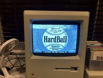
Thank you again for the exact info needed! Got some of those caps and replaced C39. Now with all new memory chips in sockets and the new C39 it has booted to the blinking question mark on the disk! Going to enjoy that for a bit before I go the next step.
Attachments
Register on MacRumors! This sidebar will go away, and you'll see fewer ads.