Become a MacRumors Supporter for $50/year with no ads, ability to filter front page stories, and private forums.
DIY 5k Monitor - success :-)
- Thread starter fiatlux
- Start date
- Sort by reaction score
You are using an out of date browser. It may not display this or other websites correctly.
You should upgrade or use an alternative browser.
You should upgrade or use an alternative browser.
Yes. If your iMac shell has an aluminium coloured Bluetooth aerial top right then the 2019 screen will fit.
Earlier shells have brass coloured aerials which don’t fit with later screens. These aerials have to be removed.
The backlight cable is different but fits in exactly the same way.
Earlier shells have brass coloured aerials which don’t fit with later screens. These aerials have to be removed.
The backlight cable is different but fits in exactly the same way.
hello mate, that's what I'm looking for. Can you please give me the link for Monitor mount you bought? Does it able to handle the weight? If you can put the details of bolts and method you used, that will be great. ThanksHey mate. I just removed the whole hinge mechanism and used a $15 monitor mount from Amazon. I just put the 2 bolts through the old hinge hole. Works perfect.
VIVO Full Motion Wall Mount for... https://www.amazon.com.au/dp/B01M99FFSP?ref=ppx_pop_mob_ap_sharehello mate, that's what I'm looking for. Can you please give me the link for Monitor mount you bought? Does it able to handle the weight? If you can put the details of bolts and method you used, that will be great. Thanks
Not sure where I had all the other bolts from. I have a bucket full of random fixings and washers etc.
It’s easily supported. Everything is removed from the iMac. The hinge mech being removed reduces a lot of the weight.
I also bolted a VESA plate to the back of the iMac case:
I bought a plate from this seller:

Once the iMac's logic board and PSU are removed the weight is considerable reduced, so finding an arm that can cope is easier.
I have a 2019 iMac 27" on another similar arm and I had to strengthen the tilt joint behind the VESA plate to cope with the weight.
This is the arm I used - cheap from eBay/Amazon, without the USB wiring:
I am building a second DIY iMac monitor and I'm using the proper Apple mount, as that is easier!
I bought a plate from this seller:
Once the iMac's logic board and PSU are removed the weight is considerable reduced, so finding an arm that can cope is easier.
I have a 2019 iMac 27" on another similar arm and I had to strengthen the tilt joint behind the VESA plate to cope with the weight.
This is the arm I used - cheap from eBay/Amazon, without the USB wiring:
I am building a second DIY iMac monitor and I'm using the proper Apple mount, as that is easier!
Last edited:
Interesting because I can use the existing arm once the weight is reduced, thanks for showing the another possibility 👍I also bolted a VESA plate to the back of the iMac case:
I bought a plate from this seller:
Once the iMac's logic board and PSU are removed the weight is considerable reduced, so finding an arm that can cope is easier.
I have a 2019 iMac 27" on another similar arm and I had to strengthen the tilt joint behind the VESA plate to cope with the weight.
This is the arm I used - cheap from eBay/Amazon, without the USB wiring:
I am building a second DIY iMac monitor and I'm using the proper Apple mount, as that is easier!
@PaulD-UK this adapter you posted seems to be nice but shipping cost to France is over £50. I need to find the EU vendor or similar item.
Yes, good pics. The AP4310 is a Dual OP Amp with voltage reference for voltage regulation. It goes to the optocouplers which are for feedback to the primary side.Are these better?
I could not find a datasheet for the DAS01A, but it's used for power management (it's not a SMC chip). It appears to be going into a similar circuit with an optocoupler.
I believe I found the connector in the schematic:
It seems that it will be enough to briefly connect the pin1 of the connector to GND. GND would be pin 2.
Since I can't see any marking, I'd suggest to simply bridge any two outer pins, which would be either pins 1+2 or pins 6+7. Bridging pins 1+2 should switch the supply on.
Bridging pins 6+7 would enable burst mode. This is a pin controlled by a power management chip, and it's either logic H via a puill-up resistor, or it's logic L. So I'm not sure should it normally bridged to GND or just left floating.
If connecting one pair of pins (i.e. either 1+2 or 6+7) to GND does not switch the supply ON, I'd suggest to try connecting both pairs to GND.
As the pull-up resistors go to +3.3V, I assume that the supply will start if pins 1+2 are connected togehter and 6+7 has no impact.
I'd be great if someone can try and report back. Maybe on the logic board side of the connector is a marking to identify pin 1?
Hello everyone,
I’m a bit new to this forum and also to this project.
I’d highly appreciate if someone could guide me through how to marry iMac speakers with the JRY-W9CUHD-AA1 board?
I started my project with buying a display (19 year model), a case, a stand and the board from Taobao.
Now I’m trying to add the camera, mic and speakers to the set up.
Do you know by chance if this board supports the same approach with the crossovers as described in the guide below?
And what is the pins wiring?
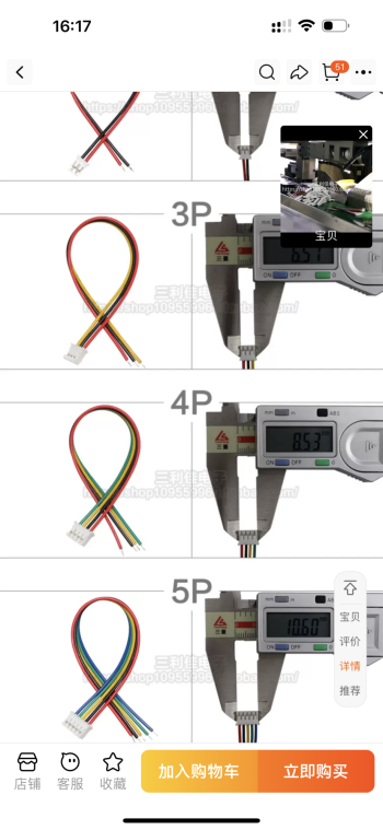
The seller of my board wasn’t very helpful (said they never assembled one). However, I understood there’s 4 pin connector on the board.
So I imagine I’ll need a connector like one I found (attached).
but I’m not sure how to match the 4 pins with the crossovers.
Second question: does this board actually support 24V?
The seller told me I’ll need 12V~6A power supply which wasn’t easy but I found (external).
However, I’m a bit concerned that may underpower, although I don’t have any plans for using USB ports on the board, except for the mic and camera that should be considerably low on power.
Third question: is anyone else experiencing that hungers are underloaded without the iMac internals, so the panel is always looking upwards?
I plan to solve it with extra dummy weight.
All in all, the “POC” worked for me but I’m currently sourcing and waiting for the components to arrive to get a full solution.
Appreciate your help.
EDIT: I’ve probable found the answer in this post
Post in thread 'DIY 5k Monitor - success") '
'
https://forums.macrumors.com/threads/diy-5k-monitor-success.2253100/post-32937652
Very helpful pictures with coloured wires 🙏🏻
I’m a bit new to this forum and also to this project.
I’d highly appreciate if someone could guide me through how to marry iMac speakers with the JRY-W9CUHD-AA1 board?
I started my project with buying a display (19 year model), a case, a stand and the board from Taobao.
Now I’m trying to add the camera, mic and speakers to the set up.
Do you know by chance if this board supports the same approach with the crossovers as described in the guide below?
And what is the pins wiring?
The seller of my board wasn’t very helpful (said they never assembled one). However, I understood there’s 4 pin connector on the board.
So I imagine I’ll need a connector like one I found (attached).
but I’m not sure how to match the 4 pins with the crossovers.
Second question: does this board actually support 24V?
The seller told me I’ll need 12V~6A power supply which wasn’t easy but I found (external).
However, I’m a bit concerned that may underpower, although I don’t have any plans for using USB ports on the board, except for the mic and camera that should be considerably low on power.
Third question: is anyone else experiencing that hungers are underloaded without the iMac internals, so the panel is always looking upwards?
I plan to solve it with extra dummy weight.
All in all, the “POC” worked for me but I’m currently sourcing and waiting for the components to arrive to get a full solution.
Appreciate your help.
EDIT: I’ve probable found the answer in this post
Post in thread 'DIY 5k Monitor - success
'https://forums.macrumors.com/threads/diy-5k-monitor-success.2253100/post-32937652
Very helpful pictures with coloured wires 🙏🏻
Attachments
Last edited:
@USB3foriMac
There is a small triangle Pin 1 marker on the interconnect cable.

Because the cable has connectors on both ends, each end has the marker on the opposite side...
However on the PSU, the pin 1 marker is on the inner end of the 7 pin connector, farthest away from the PCB edge, so bottom pin when the PSU is fitted in the iMac.
On the logic board connector, pin 1 is also marked as the bottom pin of the connector - but the cable is twisted 90º.
There is a small triangle Pin 1 marker on the interconnect cable.
Because the cable has connectors on both ends, each end has the marker on the opposite side...
However on the PSU, the pin 1 marker is on the inner end of the 7 pin connector, farthest away from the PCB edge, so bottom pin when the PSU is fitted in the iMac.
On the logic board connector, pin 1 is also marked as the bottom pin of the connector - but the cable is twisted 90º.
Last edited:
Can you also post a pic of the label of the parts under the heatsink on the component side of the connector? Just want to see what those are. Particularly the one to the edge of the PCB.@USB3foriMac
There is a small triangle Pin 1 marker on the interconnect cable.
View attachment 2370442
Because the cable has connectors on both ends, each end has the marker on the opposite side...
However on the PSU, the pin 1 marker is on the inner end of the 7 pin connector, farthest away from the PCB edge, so bottom pin when the PSU is fitted in the iMac.
On the logic board connector, pin 1 is also marked as the bottom pin of the connector - but the cable is twisted 90º.
Is it this part with red marker that needs identifying?
On the Lite-On PSU it is exposed, but on the more common Delta PSU it is concealed and can only be seen when the shroud is desoldered.
The video I got the Lite-On still from explains that the board has two PSUs on it - a less powerful Standby section, and the main 25A PSU.
So this confirms that without enabling the main PSU only 3A Standby power is available.
Last edited:
I left the power button connected to the PSU but removed the logic board connector cable. After 4 days I can report that both late-2015 iMacs I refurbished – using the old internal PSU – haven't given me any trouble yet. I am using the JRY controller board for all of my refurbished iMacs.
I actually refurbished three iMacs (I got them cheap). The first I did I created my own VESA mount and is using a cheap 12V 6A PSU, and that one is giving me trouble when it's the only display attached to my MBP. The PSU is too weak to supply power to both the Controller/LEDs *and* the MBP, so it immediately starts to flicker if the MBP isn't also attached to the 100W charger. I'll put it into the original case as well (some folks have just posted about VESA mounts, thank you!) and use the original PSU instead since it's so reliable.


EDIT: New version replacing my old crappy wooden construction with the original case, looks much nicer now.

I actually refurbished three iMacs (I got them cheap). The first I did I created my own VESA mount and is using a cheap 12V 6A PSU, and that one is giving me trouble when it's the only display attached to my MBP. The PSU is too weak to supply power to both the Controller/LEDs *and* the MBP, so it immediately starts to flicker if the MBP isn't also attached to the 100W charger. I'll put it into the original case as well (some folks have just posted about VESA mounts, thank you!) and use the original PSU instead since it's so reliable.
EDIT: New version replacing my old crappy wooden construction with the original case, looks much nicer now.
Last edited:
Hey, looks really cool, I'm also planning to setup dual monitors. Can you please explain how you able to achieve this? How did you attach your two monitors ? thanksI left the power button connected to the PSU but removed the logic board connector cable. After 4 days I can report that both late-2015 iMacs I refurbished – using the old internal PSU – haven't given me any trouble yet. I am using the JRY controller board for all of my refurbished iMacs.
I actually refurbished three iMacs (I got them cheap). The first I did I created my own VESA mount and is using a cheap 12V 6A PSU, and that one is giving me trouble when it's the only display attached to my MBP. The PSU is too weak to supply power to both the Controller/LEDs *and* the MBP, so it immediately starts to flicker if the MBP isn't also attached to the 100W charger. I'll put it into the original case as well (some folks have just posted about VESA mounts, thank you!) and use the original PSU instead since it's so reliable. View attachment 2370551 View attachment 2370553
EDIT: New version replacing my old crappy wooden construction with the original case, looks much nicer now.
View attachment 2370618
That part looks like a temperature sensor. Nope, I'm looking for the two components to the right of it.Is it this part with red marker that needs identifying?
On the Lite-On PSU it is exposed, but on the more common Delta PSU it is concealed and can only be seen when the shroud is desoldered.
The video I got the Lite-On still from explains that the board has two PSUs on it - a less powerful Standby section, and the main 25A PSU.
So this confirms that without enabling the main PSU only 3A Standby power is available.
View attachment 2370496
On the Lite-On PSU it is exposed, but on the more common Delta PSU it is concealed and can only be seen when the shroud is desoldered.
This is the best close-up I could produce of one of the parts in question obscured by the heatsink and capacitors. I can't make out any markings on the visible portion.
Easy, the one on the right is attached to a VESA mount & arm (the one seen in the picture with the wooden construction)Hey, looks really cool, I'm also planning to setup dual monitors. Can you please explain how you able to achieve this? How did you attach your two monitors ? thanks
I didn't notice the left monitor with original stand 😂. Can you please tell me what VESA and arm model you used? thanksEasy, the one on the right is attached to a VESA mount & arm (the one seen in the picture with the wooden construction)
Thanks for trying. I'd need the model number of it. Maybe using a magnifying glass.View attachment 2370722
This is the best close-up I could produce of one of the parts in question obscured by the heatsink and capacitors. I can't make out any markings on the visible portion.
But it's ok. Maybe someone can trying bridging pins 1+2 and/or 6+7 on the connector?
Thanks for trying. I'd need the model number of it. Maybe using a magnifying glass.
But it's ok. Maybe someone can trying bridging pins 1+2 and/or 6+7 on the connector?
I might have the basic skill level (and a multimeter) if given clear instructions.
With the iMac assembled (and the screen attached but not in place to keep access to the points) what would the expected results be? (Or could this be achieved without no load attached to the PSU?)
Please forgive the absolute beginner questions.
Pins 1 and 2 grounded should start the power supply and also the motherboard/computer itself?
Pins 6 and 7 should activate boost mode (over and above the output @stefan786 is seeing with his rudimentary connection)? How could this be reliably measured? At what point in the booting process?
can confirm it works. I now have a 2019 p3 panel = )Yes. If your iMac shell has an aluminium coloured Bluetooth aerial top right then the 2019 screen will fit.
Earlier shells have brass coloured aerials which don’t fit with later screens. These aerials have to be removed.
The backlight cable is different but fits in exactly the same way.
I‘ve finally got the R1811 HDMI 2.1 board from StoneTaskin to use with my iMac 27" late 2015 LM270QQ1.I have the same iMac 27" late 2015 LM270QQ1, identical panel I believe.
(SD)(B1) is not needed when making the choice.
And I also have the R1811 from StoneTaskin (with HDMI 2.0). I wanted a good one, and was less concerned about the higher price. It had everything I wanted, and I'll buy it again if I decide to build another DIY 5k display.
And the remote is quite good.
In addition, I purchased two crossover pairs for the internal speakers, that PaulD-UK posted a while back. One extra pair, in case I do another build.
And StoneTaskin gave me a fantastic support, when it turned out the cable was faulty. They shipped a replacement and gave me advice and additional information, I didn't have at first.
I have documented all of this in here
I’ve got everything removed from the inside of the iMac and want to hook the board up to my display for a quick test to make sure everything works. I’m a bit unclear as to the wiring of the backlit cable after having looked at the diagram on StoneTaskin’s site (attached) and just wanted to run a quick question by you to make sure I get this hooked up correctly. I’ll just list these below.
Question: StoneTaskin sent me a “backlit” cable. One end of the cable has two small connectors. The diagram on their site shows just a single small connnector (see picture). I’m assuming the 2 small connectors go in the slots indicated in the photo of my iMac. Is this correct? Does it matter which “order” the two connectors are attached (ie can either connector go into either spot)?
Other than this, I think I’ve got everything else hooked up correctly. Just don‘t want to blow It by putting these two small connectors in the wrong spot.
Thanks for any help on this.
Last edited:
Good questions. As I neither have one nor a schematic diagram, there is a bit of guessing involved.I might have the basic skill level (and a multimeter) if given clear instructions.
With the iMac assembled (and the screen attached but not in place to keep access to the points) what would the expected results be? (Or could this be achieved without no load attached to the PSU?)
Please forgive the absolute beginner questions.
Pins 1 and 2 grounded should start the power supply and also the motherboard/computer itself?
Pins 6 and 7 should activate boost mode (over and above the output @stefan786 is seeing with his rudimentary connection)? How could this be reliably measured? At what point in the booting process?
Since it was mentioned that the supply works continuously, a test would be quite simple really.
If 12V are present without any intervention, it can be used to power whatever is connected. If the supply goes into current limit, the voltage would drop, and the connected equipment would undergo a power reset.
So let's come up with a sequence of actions of what can/needs to be done:
1. If - without intervention - the connected board(s) work fine, nothing at all needs too be done.
2. If the connected devices do not start up at all (no power present), then shorting pin 1 with 2 (pressing and holding power button) would be the most reasonable option. If subsequently the connected devices work fine, the following test could be done to confirm how the supply operates:
Open the connection between pins 1 and 2 (release power button). If the supply stops, it means pin 1 and 2 need to be shorted while operation (needs a power switch rather than a button). If the supply continues, it would behave same as previous supplies (I.e. pushbutton is fine). So after this, we know.
3. If the connected devices start up but go through power reset as some point (supply in Power Limit mode), then shorting pin 6 with 7 would be the most reasonable option. If subsequently the connected devices work fine, the following test could be done to confirm how the supply operates:
Unplug to power cord to completely power off the supply. Bridge pins 6 and 7 (bridge with wire/switch). Plug in the power cord. See whether supply powers up (it shouldn't). Bridge pins 1 and 2 (press and hold power button). You should have full power now. Remove bridge between 1 and 2 (release power button). If unit remains on, find. Try a shutdown, wait for screen to go into standby, them measure the power dissipation with a power meter on the screen's AC socket.
Repeat above, with the difference that you open the bridge between 6 and 7 at the end, and wait for the screen to go into standby. Check the power dissipation, and compare with the earlier measurement. If there is a huge difference, you'd, need to implement a switch-oof mechanism (e.g. switched AC socket, or a switch on 6 and 7). I believe that it will be ok to keep 6 and 7 bridged if that's needed in the first place.
Register on MacRumors! This sidebar will go away, and you'll see fewer ads.