I’m replying to my own post. I searched back in this thread and found this photo of from “Regulus67” back in August 2023…showing how the backlit connector needs to plug into the R1811 board.I‘ve finally got the R1811 HDMI 2.1 board from StoneTaskin to use with my iMac 27" late 2015 LM270QQ1.
I’ve got everything removed from the inside of the iMac and want to hook the board up to my display for a quick test to make sure everything works. I’m a bit unclear as to the wiring of the backlit cable after having looked at the diagram on StoneTaskin’s site (attached) and just wanted to run a quick question by you to make sure I get this hooked up correctly. I’ll just list these below.
Question: StoneTaskin sent me a “backlit” cable. One end of the cable has two small connectors. The diagram on their site shows just a single small connnector (see picture). I’m assuming the 2 small connectors go in the slots indicated in the photo of my iMac. Is this correct? Does it matter which “order” the two connectors are attached (ie can either connector go into either spot)?
Other than this, I think I’ve got everything else hooked up correctly. Just don‘t want to blow It by putting these two small connectors in the wrong spot.
Thanks for any help on this. View attachment 2371312 View attachment 2371313
Become a MacRumors Supporter for $50/year with no ads, ability to filter front page stories, and private forums.
DIY 5k Monitor - success :-)
- Thread starter fiatlux
- Start date
- Sort by reaction score
You are using an out of date browser. It may not display this or other websites correctly.
You should upgrade or use an alternative browser.
You should upgrade or use an alternative browser.

Please be careful with the display cable. As it is so stiff in the end shown in the photo, I believe it breaks easily if bent up or down.I‘ve finally got the R1811 HDMI 2.1 board from StoneTaskin to use with my iMac 27" late 2015 LM270QQ1.
I’ve got everything removed from the inside of the iMac and want to hook the board up to my display for a quick test to make sure everything works.
My first attempt would not turn on the display. On my third attempt, I noticed smoke, and a tiny hole developing in that sleeve.
StoneTaskin 🥰 shipped me a new replacement cable, and I have had no issues since.
Last edited:
Thanks for the tip! I’ll keep that in mind and be careful as I’m maneuvering the board around as I’m mounting it inside the iMac case. Now that I’m through wiring the R1811, I’ll share my thoughts with others who buy this particular board.Please be careful with the display cable. As it is so stiff in the end shown in the photo, I believe it breaks easily if bent up or down.
My first attempt would not turn on the display. On my third attempt, I noticed smoke, and a tiny hole developing in that sleeve.
StoneTaskin 🥰 shipped me a new replacement cable, and I have had no issues since.
View attachment 2371363
- The display cable:
- Great tip from ”Regulus67” on the stiffness of the connector on the end that plugs into the board. I’ll be aware of this when I go to mount the board.
- I found the other end of this cable to be just the opposite (ie lacking of any structure where the connector plugs into the iMac’s port). This makes it difficult to just slide it right into the connector. Instead, you have to use some sort of tool…on the back side of the connector to help push it in. With the connector so “flimsy” on this end, it feels like you might be pushing on the wiring as your doing this. So, be careful here as well.
- The Backlit cable:
- I found this to be the toughest cable to connect (ie on the end that connects to the iMac’s backlit connector cable). It’s almost impossible to tell which way to orient the cables As there are no visual cues. With only a 50/50 shot, I gave it a try. I “think” my first attempt was that i had the cable oriented the wrong way as the insertion was very stiff (required a lot of force)…and…once in…the connection did not seem flush and woud not sit “flat” across the two connectors. So, I tried it the other way and it went in flush and both connectors (ie iMac’s and StoneTaskins) would lay “flat” after connection. I found this very tricky.
- I guess I won’t know if I damaged one of the connectors (ie the iMac‘s or the StoneTaskin) until I test it today.
- I found this to be the toughest cable to connect (ie on the end that connects to the iMac’s backlit connector cable). It’s almost impossible to tell which way to orient the cables As there are no visual cues. With only a 50/50 shot, I gave it a try. I “think” my first attempt was that i had the cable oriented the wrong way as the insertion was very stiff (required a lot of force)…and…once in…the connection did not seem flush and woud not sit “flat” across the two connectors. So, I tried it the other way and it went in flush and both connectors (ie iMac’s and StoneTaskins) would lay “flat” after connection. I found this very tricky.
- Instructions:
- There were no instructions that came with my R1811. I ordered directly from Stontaskin. This made the assembly overly tricky. At this price, they really should include some clear instructions.
- I saw from a post by “Regulus67” they he had asked for and received some excellent high resolution photos showing how the key connections needed to work. This would have helped me tremendously. I didn’t think to ask them. They really should include this with every kit.
@DSTOFEL You've got the picture of the backlight cable connection from @Regulus67:
As you see in that pic, if the 3 moulding circles on the iMac screen backlight connector face you, the edge red wire should be on the right.
There are two different R1811 b/l cables connectors, and the stubby one is more difficult to plug in.
Use long-life insulating tape to keep the connection firmly held together.
If the connection falls apart whilst the R1811 is powered up, and the pins short to the iMac case YOU WILL DAMAGE THE R1811.....
Thanks so much. When I tested the display this morning, the green light comes on the (ie on the remote board) and the display shows as a second display on my Mac Book Pro, however, the display is just black (ie nothing coming from it). I’m wondering if I’ve got one or both of the backlight connectors plugged in the wrong way.@DSTOFEL You've got the picture of the backlight cable connection from @Regulus67:
As you see in that pic, if the 3 moulding circles on the iMac screen backlight connector face you, the edge red wire should be on the right.
There are two different R1811 b/l cables connectors, and the stubby one is more difficult to plug in.
Use long-life insulating tape to keep the connection firmly held together.
If the connection falls apart whilst the R1811 is powered up, and the pins short to the iMac case YOU WILL DAMAGE THE R1811.....
From the picture above, does it look like the backlight connector (ie that plugs into the iMac’s cable) is backwards. The red wire (when facing me) is on the “left”.
Also, I’m not sure on the orientation for the LCD display connector (ie the side that plugs into the iMac). From the pic’s below, should I plug it in on the picture labeled “A”….or per the picture labeled “B”?
Thanks again for the help,
Last edited:
Thanks for your help!. I switch the backlight connector around and it works! Victory!!!@DSTOFEL
Hi.
Your backlight cable is the wrong way round.
The outer red wire should insert into a gray wire
The main eDP cable should be inserted as in pic A. The wire clamp is clipped behind the connector once it is inserted.
The continuous metal side is visible, not the slotted side.
Now, I’ll just mount the board inside the iMac and tape down the display until the speaker crossover kit arrives.
I've been using a R9A18 with my 2015 iMac for the last year, but recently the screen started strobing when it came on, and now refuses to come on at all. Also the LED on the keyboard attachment just flashes RED. Has the board gone bad, or is it my LCD?
It is great you made a list DSTOFEL and PaulD-UK pointing out corrections 🥰
Because it is a monumental task for anyone joining this thread, and wanting to use the R1811. With so many pages to search through. Every time we "update" the information collected in this thread, it helps others who are in doubt.
Well done 👍
Because it is a monumental task for anyone joining this thread, and wanting to use the R1811. With so many pages to search through. Every time we "update" the information collected in this thread, it helps others who are in doubt.
Well done 👍
Thanks! After all of the great help I‘ve gotten from you, PaulD and others on this thread, I’m glad I could contribute just a bit!!It is great you made a list DSTOFEL and PaulD-UK pointing out corrections 🥰
Because it is a monumental task for anyone joining this thread, and wanting to use the R1811. With so many pages to search through. Every time we "update" the information collected in this thread, it helps others who are in doubt.
Well done 👍
The quality of the iMac’s 5K display blows me away when compared with my 2018 15 inch MacBook Pro. Night and Day. Buster Scruggs has never looked better😊
Once the speaker crossover kit arrives, I‘ll re-install the iMac speakers and then seal it back up once everything proves out.
The only “finiky” thing seems to be the IR. Is this a “line of sight” IR that needs to be mounted outside of the IMacs case?
Last edited:
I've been using a R9A18 with my 2015 iMac for the last year, but recently the screen started strobing when it came on, and now refuses to come on at all. Also the LED on the keyboard attachment just flashes RED. Has the board gone bad, or is it my LCD?
The other potential culprit, in addition to the LCD and the driver board, is your power supply. If you happen to have a spare 12V power supply lying around to test you may be able to eliminate one suspect. (Or test the supply on another 12V device like an external HDD or powered speakers)
The only “finiky” thing seems to be the IR. Is this a “line of sight” IR that needs to be mounted outside of the IMacs case?
Yes, I would be surprised if it could function at all inside the case.
Since IR transmission is a wireless protocol based on a type of light, it requires a clear line of sight between the transmitter (the remote) and the receiver. This means it can’t transmit through walls or ceilings, unlike WiFi or Bluetooth.
The iMac has antennas for WiFi and Bluetooth.
But not an IR Photodiode, which is built into the control board supplied with the R1811
I don’t have any problems with my I/R receiver installed inside the case with the Control Strip at the back.
I’ve fitted the dark brown plastic that was used in an old set top box in front of the receiver which allows the I/R through.
It works fine if I use the remote control about 6 inches away and slightly below the screen from the front.
There is a row of metal cased hard drives behind the monitor that the I/R signal reflects off to hit the sensor.
Last edited:
Yes, I would be surprised if it could function at all inside the case.
Since IR transmission is a wireless protocol based on a type of light, it requires a clear line of sight between the transmitter (the remote) and the receiver. This means it can’t transmit through walls or ceilings, unlike WiFi or Bluetooth.
The iMac has antennas for WiFi and Bluetooth.
But not an IR Photodiode, which is built into the control board supplied with the R1811
Thanks for the feedback on this. After I get the speaker crossover kit I’ve ordered and re-install the iMac’s speakers, I’ll figure out a good place for this control strip before I button things up so that I can use the remote when needed.I don’t have any problems with my I/R receiver installed inside the case with the Control Strip at the back.
I’ve fitted the dark brown plastic that was used in an old set top box in front of the receiver which allows the I/R through.
It works fine if I use the remote control about 6 inches away and slightly below the screen from the front.
There is a row of metal cased hard drives behind the monitor that the I/R signal reflects off to hit the sensor.
Does anyone have info on the included mini keyboard and what the LED light codes are?I've been using a R9A18 with my 2015 iMac for the last year, but recently the screen started strobing when it came on, and now refuses to come on at all. Also the LED on the keyboard attachment just flashes RED. Has the board gone bad, or is it my LCD?
The only mention of blinking red lights in this thread is with a power supply which blinked red when a different (4K equivalent of R9A18) video board got its backlight cable shorted.
The PSU switched on - flash red - then immediately detected the short circuit on the board and switched itself off.
It then tried again to switch on, and again turned off immediately....
The instructions for use (link to data sheet) of the R1811 just says:
"Pay Attention that 24V or 12V power adapter nominal output current is greater than
the The sum of current consumption between board and panel. If the power supply
shortage will cause the product does not work properly."
So. a PSU failure is the first thing to check
Last edited:
You're right, it was the power supply. It was dimming in unison with the display keypad LED, so I replaced it and the display came back. Thanks for your tip!The only mention of blinking red lights in this thread is with a power supply which blinked red when a different (4K equivalent of R9A18) video board got its backlight cable shorted.
The PSU switched on - flash red - then immediately detected the short circuit on the board and switched itself off.
It then tried again to switch on, and again turned off immediately....
The instructions for use (link to data sheet) of the R1811 just says:
"Pay Attention that 24V or 12V power adapter nominal output current is greater than
the The sum of current consumption between board and panel. If the power supply
shortage will cause the product does not work properly."
So. a PSU failure is the first thing to check
I've been using a R9A18 with my 2015 iMac for the last year, but recently the screen started strobing when it came on, and now refuses to come on at all. Also the LED on the keyboard attachment just flashes RED. Has the board gone bad, or is it my LCD?
The other potential culprit, in addition to the LCD and the driver board, is your power supply. If you happen to have a spare 12V power supply lying around to test you may be able to eliminate one suspect. (Or test the supply on another 12V device like an external HDD or powered speakers)
You're right, it was the power supply. It was dimming in unison with the display keypad LED, so I replaced it and the display came back. Thanks for your tip!
You're welcome.
That would work fine.
If you connect the PC to the USB-C port on the R1811 you would need a bi-directional cable - not all cables work both ways.
You could connect the PC with a DP 1.4<>DP 1.4 cable, and connect the Mac mini with a video-capable USC-C/TB3 or 4 cable.
There are no recent reports of problems or damage of the Mac's USB-C port by connecting this way.
Hello mate, I just received the R1811 and noticed that it has 3 DP all together. Do all 3 DPs have the same capacity so that I can connect to 2 macs and a windows machine using DP? thanks
Attachments
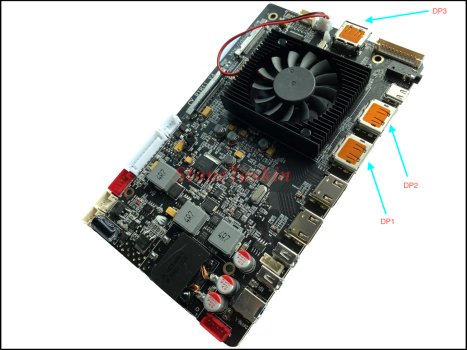
thanksThe DP3 socket on the side is not an input, it's an MST output used to daisy chain an additional DP monitor.
MacOS doesn’t support MST.
Only Windows works with this output.
MacOS may give a mirrored output?
Thank you guys for the wonderful support. I've successfully managed to get the display working. Fan is noisy and spinning all the time. I'm feeling that color is little bit high. Can someone please share the setting specially for the color calibration?
Attachments

Hi everyone! Small update, but just wanted to share that my monitor is still working great! Having the speakers and board in this configuration caused some overheating, which bummed out the power supply! I took the speakers out and rearranged the layout for better airflow, and the monitor doesnt even get warm, unless I crank the brightness to max.Thank you to everyone for the help! My rig is finally complete! This was my first DIY project, so I was bit nervous but still excited to dive in. Using Gold's setup as inspiration, I ended up installing an 8-speaker system as well, with a temperature control system. Just wanted to give some of my thoughts and add some other tips and perspective.
View attachment 2143506
Power:
For the iMac cables, I ended up soldering to the back of the power switch. The pins at the cable portion were so close together that it made sense to use the pins that were more spaced out. I verified with a multimeter that the positive side has continuity with the power (pin 4), and the negative with the ground (pin 3).
View attachment 2142985
To retain the original power supply, I used self solder connectors. In hindsight, I probably would have soldered first, but I only learned to solder after doing that part and wasn't confident on it yet.
I really like the Alitove power supply units. I ended up using that for the 24V supply. Funnily enough, the 5A unit is bigger than the 6A unit. The 6A fits nicely between the posts as shown, while the 5A is just too big to fit snugly there. With all the extra components I added, it worked out nicely to just go for 6A. The 18V supply needed for the amp works really nice as well. For the amp, it ranged from 12-19V, with 16V recommended. It's tough to find a 16V supply without needing a converting plug piece (all I saw for 16V were for some printers/scanners, which had the wrong size for the plug adapter). Alitov's 19V was too big to justify, compared to the one I ended up getting, so it ended up just saving space in the long run.
View attachment 2142971
Audio:
I used a 2 x 15W + 30W amplifier, which had enough terminals to install the full 8-speaker system easily. Initially I was going to hook resistors in parallel to help achieve 8 ohms in every speaker, but the power consumption that the resistors draw would have made the system worse off, so I just connected the speakers in series. The woofers end up at the 8 ohms, and while the speakers are at 12 ohms, it is plenty powerful.
View attachment 2142986
For the terminals, I highly suggest using ferrule crimps, as it makes it look nice and clean, without any risk of wires touching each other. I did notice them falling off at first, because the wires are pretty small. I also crimped the plastic piece to ensure a good connection. I didn't bother seeing if the on-board speaker connection worked or not, and it seems to be mislabeled in the first place, and the amplifier does a great job. I also cut some plexiglass and sanded it down, to attach to the botton of the amp. I wanted to ensure that no metal contact would be made, so I added that extra layer of security. The wires in the extra speakers are far too long for the Left side, so I cut that down and used it extend the cables on the right.
As for the imac speakers, I think the diagram of which connector is which is wrong, as the tweeter cables controlled the woofer and vice versa, according to my labels. Some of my labels did fall off (ughhhh haha) so I doubled checked the polarity of the woofer, using a 9V battery, and made sure the speaker moved outward when I connected. The tweeter was harder to verify, since it doesn't move noticeably. I simply played trial and error by connecting all four speakers up. I tested every permutation, and the one that sounded best was the correct one, as the others phased out elements of the sound, making it sound awful.
View attachment 2142976
Temperature:
I was going back and forth on if I should install the temp control rig. Gold verified that the system doesn't really get hot enough to necessarily warrant it, but I was not sure how much heat the amplifier would generate, since mine can output 20w more than the Dollatek amplifier Gold used, so I decided to go for it. I actually found this part really easy. I used a Noctua 80mm as well. I had the 4-pin but it doesn't matter; you only need two of the cables.
This site is fantastic for understanding the W1209 board. Gold's amplifier has a power out, but mine didn't, so I spent some time trying to figure out how to power this joint. For power, because I pulled the factory fan, there was a convenient 12V power connector right on the board, saving me from having to buy another supply. To connect the fan, I simply cut the yellow and black wire from the fan (I then securely taped the green and blue wires), and cut the cable from the stock fan, so you don't have to buy two pins connectors.
From left to right the cables connect:
![image-35.jpeg]()
K0: The yellow wire from the fan
K1 and +12V: Split the red wire from the stock fan connector into 2, and connect to each respective terminal
GND: Combine the black ground cable from the fan and stock fan connector
I also used ferrule crimps here.
I set the temperature to 70C, the hottest it's gotten for me so far is low 40s, but the system works seamlessly, and you don't have to change any other settings.
View attachment 2142973
Installation:
I used velcro to put the components in place. It is extremely strong velcro, and I have no worries of anything falling out. Trying to plan out the system was challenging, but I found a good layout in the end. Unfortunately it only allows me to connect the thunderbolt cable, but I don't mind. If that's a big deal to you, there might be a different layout that works, but with all of my extra components, including the extra LED backlight it was a sacrifice that I had to make. I also needed a right angle extension for the power supply on the board, as the straight connection did not fit.
For the controller strip, I drilled holes into the front. I was nervous the drill would bend the front panel, but it's plenty sturdy, especially since I applied upward force against it. Because of this, I actually hand-drilled the hole initially, then expanded them. I'd say you don't really need to do this, but if you want the most accurate, I would recommend it. It's a alot of work but pays off. I noticed without hand-drilling, even with a nice center punch, the drill would more likely veer off slightly; this happened with the holes that I used for the screws, cuz I was dreading having to hand-drill two more holes. For the drill bits, the holes for the buttons were 1/4 ; the hole for the LED was 3/16; and the holes for the screws were 9/64
To protect the strip from some of the metal, I deburred the hole as a best as I could, then placed a piece of electrical tape to line up with the hole. THIS was a pain in the ass, as there is no room to line the tape up to the hole, as I cut the holes into the tape first (highly recommended, so you can really get a clean hole in the tape). Initially I was just going to tape the strip once it was lined up to the holes, but there's not a lot of room to really latch the tape onto. Conveniently, the strip has holes for mounting, so I used two nylon screws with a nut to secure it in place. It's very secure! I also put some push-button caps to make it look nice and make using the button easier, glued with some E6000.
View attachment 2143370
Quick aside: for the iMac power button, make sure it's cable is in FRONT of the left speaker, otherwise the cable gets in the way of the pushing mechanism and the button won't feel tactile and it will be very gummy.
Unfortunately, the ports are just too small to get the Thunderbolt 3 cable through. I used a hacksaw blade, bent it 90 degrees so I could hold it on the other side, and cut the USB-C and Ethernet port together. I put some electrical tape to protect the cable, then aluminum tape along everything, to make it look a bit sleeker.
View attachment 2143371
Thank you to everyone who helped me out, Paul, Citivilous, David and YaoSiang; and and tdiggity and hybridfrost on Reddit!
Links:
R1811 Board:

Recycle 27" 5K Panel LM270QQ1-SDA2/B1/C1...-LCD Driver Board Kit DP1.4 w Remote | eBay
The DP interface supports the DP1.1, DP1.2, and DP1.4 protocols support hard decoding of 5K @ 60HZ and 4K @ 144Hz signals and supports the DP ring connection function. Original charging cable is not sufficient for 5K.www.ebay.com
LED Backlight Driver:

Led Backlight Driver DZ-LP0818 Improving Brightness for LM270QQ1/LM270QQ2... | eBay
1 X led backlight driver board.www.ebay.com
Stonetaskin Speakers:

18.0US $ 10% OFF|Stonetaskin High Quality Audio Speaker For R9513 R9516 R9a18 R1811 Panel 5k Driver Board Speaker 8 Ohm 10w 100% Tested - Pc Hardware Cables & Adapters - AliExpress
Smarter Shopping, Better Living! Aliexpress.comwww.aliexpress.us
Audio Amplifier:

SZHFJCTH Audio Amplifier Board with 15W×2+30W 2.1 Channel Subwoofer Amplifier Board, DC12-19V Audio Component amplifiers for Store Solicitation Home Theater Square DIY Speakers
SZHFJCTH 2.1 amplifier board 15W×2+30W(4-8ohms)audio amplifier board, DC12-19V,audio component amplifiers for Store Solicitation Home Theater Square DIY Speakerswww.amazon.com
Headphone Cable:

Cable Matters 2-Pack 3.5mm Audio Cable 3 ft (3.5mm Aux Cable/Aux Cord, Headphone Cable, Audio Cable 3.5mm Male to Male) - 3 Feet / 0.9 Meters
Cable Matters 500101-BLK-3x2 stereo jack cableswww.amazon.com
W1209 Temperature Control Board:

HiLetgo 2pcs W1209 with Case 12V DC Digital Temperature Controller Board Micro Digital Thermostat -50-110°C Electronic Temperature Temp Control Module Switch with 10A One-Channel Relay and Waterproof
HiLetgo 2pcs W1209 with Case 12V DC Digital Temperature Controller Board Micro Digital Thermostat -50-110°C Electronic Temperature Temp Control Module Switch with 10A One-Channel Relay and Waterproofwww.amazon.com
Noctua NF-A8 PWM:

Noctua NF-A8 PWM, Premium Quiet Fan, 4-Pin (80mm, Brown)
The NF-A8 is a highly optimised, premium quality quiet 80mm fan. Featuring Noctua’s AAO (Advanced Acoustic Optimisation) frame as well as sophisticated aerodynamic design measures such as Flow Acceleration Channels, the NF-A8 further improves the renowned quiet cooling performance of the award-wi...www.amazon.com
iFixit Adhesive Strips:

iFixit Adhesive Strips Compatible with iMac Intel 27" (2012-2019) - Repair Kit
iFixit Adhesive Strips Compatible with iMac Intel 27" (2012-2019) - Repair Kitwww.amazon.com
Alitove 24V 6A Power Supply:

ALITOVE 24V 6A Power Supply Adapter Converter 100-240V AC to DC 24 Volt 144W 6Amp 5.5A 5A 4A Transformer with 5.5x2.5mm Plug for LED Strip Light CCTV Camera LCD Monitor Massage Chair
ALITOVE 24V 6A Power Supply Adapter Converter 100-240V AC to DC 24 Volt 144W 6Amp 5.5A 5A 4A Transformer with 5.5x2.5mm Plug for LED Strip Light CCTV Camera LCD Monitor Massage Chairwww.amazon.com
18V Power Supply:

KFD 18V Universal AC Power Charger DC 2.69A (2.5A/2A/1.5A/1A Compatible) Barrel DC Plug 5.5x2.1mm with 7 Tips 6.5x4.4mm/ 5.5x3.0mm/ 5.5x2.5mm/ 4.8x1.7mm/ 4.0x1.7mm/ 3.5x1.35mm/ 2.5x0.7mm Power Supply
KFD 18V Universal AC Power Charger DC 2.69A (2.5A/2A/1.5A/1A Compatible) Barrel DC Plug 5.5x2.1mm with 7 Tips 6.5x4.4mm/ 5.5x3.0mm/ 5.5x2.5mm/ 4.8x1.7mm/ 4.0x1.7mm/ 3.5x1.35mm/ 2.5x0.7mm Power Supplywww.amazon.com
Power Supply Splitter:

Toptekits C14 to C13+C7 Y Splitter Power Plug Cord,Single IEC 320 C14 Male to C13+C7 Female Splitter Adapter Cable Cord(C14 to C7+C13 1ft)
Single C14 To C13 + C7 Y Type Splitter Adapter Cable Socket Adapter Can be used for remote power PDUs or power strips connected to servers with dual power supplies AC power cords offer PC users a solution to their power connectivity problems. Plug type: IEC-320-C14 (male) to C13+C7 (female) Color...www.amazon.com
Right-Angle Power Extension Cable:

Fancasee 2 Pack 5.5mm x 2.5mm DC Power Extension Cable 90 Degree Right Angle Male to Female Plug Jack Extension Cord for IP Camera CCTV Security Camera Surveillance LED
5.5mm x 2.5mm L-Shape DC power supply extension cable, convert straight plug to 90 degree right angle plug, male to female plug jack connector extension cord. The 90 degree right angle plug jack cable can be easily go through the narrow gap, will never bend and damage the power supply cord. This ...www.amazon.com
Nylon Screws and Bits:

QTEATAK M3 White Nylon Plastic Pan Round Head Screws, Nut Bolts, Gasket Assortment Kit(Metric M3: 6mm 8mm 10mm 12mm 15mm 20mm 25mm)
QTEATAK M3 White Nylon Plastic Pan Round Head Screws, Nut Bolts, Gasket Assortment Kit(Metric M3: 6mm 8mm 10mm 12mm 15mm 20mm 25mm)www.amazon.com
3M Fasteners:

3/4" 3M Back-Glue Self Adhesive White Strong Cable Zip Tie Mounts 100pcs with 8" Ties, Screws, Outdoor Sticky Wire Fasteners Cable Clips Management Anchors Organizer Holders Squares
product manual: Adhesive cable clips with self-adhesive pads for stable grip on the surface for easy removal without damaging the table top and no residue on the surface This 100piece self-adhesive 3M Super glue cable tie base will help you manage power line management and organize multiple cable...www.amazon.com
Velcro:

VELCRO Brand Heavy Duty Tape | 12 Foot Roll | Strong Sticky Back Adhesive Holds up to 10 lbs | Industrial Strength Fasteners for Indoor or Outdoor Use | 1-1/2in Width, White (VEL-30837-USA)
VELCRO Brand Heavy Duty fasteners are the most versatile tool in your toolbox. Need to get your basement in order? Heavy Duty VELCRO Brand Industrial Strength fasteners to the rescue. Organizing the garage? Industrial Strength VELCRO Brand fasteners will stick to most smooth surfaces, powering th...www.amazon.com
Thunderbolt 3 Cable:

Cable Matters [Intel Certified] 20Gbps Thunderbolt 3 Cable 6.6 Feet (USB C Thunderbolt Cable) in Black Supporting 100W Charging
Thunderbolt 3 dating usb-c The Cable Matters 1 meter Thunderbolt 3 cable connects to any Thunderbolt 3 or USB-C port on a computer, docking station or monitor. This certified cable carries twice the bandwidth of a USB-C cable using the same reversible connector. Thunderbolt, USB and DisplayPort c...www.amazon.com
Drill Bits (AWESOME for metal):

DEWALT Drill Bit Set, 14-Piece, 135 Degree Split Point, Titanium Nitride Coated, For Plastic, Wood and Metal (DW1354)
Our IMPACT READY Titanium Nitride Coated drilling accessories now come in ToughCase+ system, the latest addition to our acccessory storage line. The ToughCase+ system is a connectable case system designed to optimize storage space and keep your bits organized. The patented bit-bar design of the T...www.amazon.com
Deburring Tool:

AFA Tooling - Deburring Tool with 10 Extra High Speed Steel Swivel Blades - Works on Metal, Resin, PVC Pipes, Copper, Plastic and 3D Printed Edges - Plumbing & 3D Printing Burr Removal Reamer Tool
AFA Tooling - Deburring Tool with 10 Extra High Speed Steel Swivel Blades - Works on Metal, Resin, PVC Pipes, Copper, Plastic and 3D Printed Edges - Plumbing & 3D Printing Burr Removal Reamer Toolwww.amazon.com
Ferrule Crimping Tool and Crimps:

Ferrule Crimping Tools Wire Pliers - 1800 PCS Wire Ferrules with Crimpers Pliers Kit for Electricians, Adjustable Ratchet Tools with Terminals Connectors AWG 28-7, 0.08-10mm²
Ferrule Crimping Tools Wire Pliers - 1800 PCS Wire Ferrules with Crimpers Pliers Kit for Electricians, Adjustable Ratchet Tools with Terminals Connectors AWG 28-7, 0.08-10mm²www.amazon.com
Push-button Caps:

Cylewet 35Pcs 6×6×9mm Tactile Tact Push Button Switch Micro Switch Touch Switch with Button Caps of 7 Color for Arduino (Pack of 35) CYT1052
Cylewet 35Pcs 6×6×9mm Tactile Tact Push Button Switch Micro Switch Touch Switch with Button Caps of 7 Color for Arduino (Pack of 35) CYT1052www.amazon.com


Attachments

Last edited:
Your image attachment is broken (for me at least)Hi everyone! Small update, but just wanted to share that my monitor is still working great! Having the speakers and board in this configuration caused some overheating, which bummed out the power supply! I took the speakers out and rearranged the layout for better airflow, and the monitor doesnt even get warm, unless I crank the brightness to max.
![img_0957-jpeg.2373122]()
Register on MacRumors! This sidebar will go away, and you'll see fewer ads.